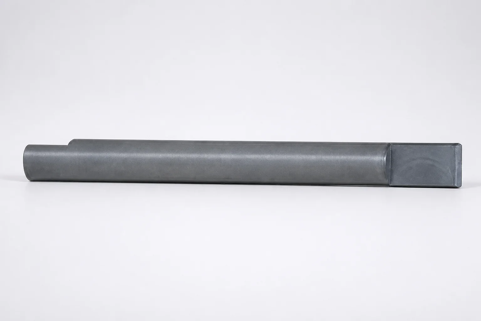
Inclined Direct Push-Up Lifter Pins - Key Flats
Inclined Direct Push-Up Lifter Pins - Key Flats deliver reliable guidance for loose cores by using precision key flats that maintain alignment during lift and insertion. Built for smooth handling, they help improve assembly efficiency while reducing wear on precision systems.
- Key flats design supports stable positioning for consistent core insertion
- Engineered push-up pin geometry improves insertion/removal efficiency in assembly
- Durable construction helps minimize wear and protect sensitive mold components
- Compatible with loose cores such as SCY and SCZN / SCZA for inclined lifter applications
Specifications
12 configurations available
| D (Applicable inclined pin diameter) (mm) | Applicable loose core part number | L (L dimension) (mm) | F (Length of inclined block side double chamfering) (mm) | W (Width of inclined block side double chamfering) (mm) | type |
|---|---|---|---|---|---|
| 12 | SCZN・SCZA | 100 ~ 800 | 10 ~ 50 | 3 ~ 10 | - |
| 16 | SCZN・SCZA | 100 ~ 800 | 10 �� 50 | 6 ~ 14 | - |
| 20 | SCZN・SCZA | 100 ~ 800 | 10 ~ 50 | 12 ~ 18 | - |
| 25 | SCZN・SCZA | 100 ~ 800 | 10 ~ 50 | 15 ~ 23 | - |
| 30 | SCZN・SCZA | 100 ~ 800 | 10 ~ 50 | 20 ~ 28 | - |
| 8 | SCY | 100 ~ 600 | 10 ~ 50 | 3 ~ 7 | - |
| 10 | SCY | 100 ~ 800 | 10 ~ 50 | 3 ~ 8 | - |
| 12 | SCY | 100 ~ 800 | 10 ~ 50 | 3 ~ 10 | - |
| 16 | SCY | 100 ~ 800 | 10 ~ 50 | 6 ~ 14 | - |
| 20 | SCY | 100 ~ 800 | 10 ~ 50 | 10 ~ 18 | - |
| 25 | SCY | 100 ~ 800 | 10 ~ 50 | 15 ~ 23 | - |
| 30 | SCY | 100 ~ 800 | 10 ~ 50 | 20 ~ 28 | - |
Product Guide
Application Scenarios+
Inclined direct push-up lifter pins with key flats are used in mold tooling where loose cores must be guided smoothly during opening/closing. The key-flat alignment helps keep the core orientation stable while the inclined geometry performs controlled lift-and-insertion, reducing misalignment and binding at the transition.
Common scenarios include:
- Automotive and industrial connector housings: use these pins to guide loose core features that require repeatable positioning, improving cycle stability during assembly and ejection.
- Electronics and appliance housings: inclined lifter applications benefit from the smooth push-up action and the key-flat stabilization, which helps protect precision mating surfaces.
- Complex undercut or slide-related inserts: for loose cores such as SCY and SCZN / SCZA, the key flats support consistent insertion/removal under inclined lifter motion.
This variant is suited because the key flats maintain alignment for the specified loose-core part families, enabling reliable assembly operations across the listed size ranges.
Material & Process Details+
The provided specifications for this product focus on geometry and compatibility; no steel grade, hardness (HRC), or heat-treatment state is listed in the input data. For engineering selection, confirm the actual pin material and heat treatment from the manufacturer’s product specification sheet for SKU 110200174050.
In typical lifter-pin applications, the material choice balances wear resistance (for repeated sliding contact and chamfer interaction) against toughness (to prevent chipping under side load during inclined motion). If multiple material options exist for the same geometry in your procurement channel, compare them by:
- Hardness (HRC): higher hardness improves abrasion resistance but may reduce impact toughness.
- Surface treatment: nitriding or similar surface hardening can increase wear life while maintaining a tougher core.
- Heat treatment condition: verify whether the pins are pre-hardened or quenched & tempered to ensure predictable dimensional stability.
Use the confirmed grade/hardness to finalize wear-life and contact-surface strategy.
Sizing & Selection Guide+
Select the lifter-pin size by matching the inclined pin diameter (D), the L length, and the chamfer block geometry (F and W) to your mold’s inclined lifter path for the target loose core.
- Diameter D (mm): choose within 8 ~ 30 mm based on the required clearance and the mechanical interface to the loose core.
- Length L (mm): select from 100 ~ 800 mm (or 100 ~ 600 mm, depending on the applicable configuration) to ensure full engagement during push-up and retraction.
- Chamfer dimensions: match F (10 ~ 50 mm) (inclined block side double chamfer length) and W (3 ~ 20 mm) (inclined block side double chamfer width) to the inclined block and contact zone profile.
For fit, design mating features around the selected diameter and chamfer widths so the key-flat alignment engages without excessive clearance. If your mold requires tight positional repeatability, account for normal manufacturing tolerances on the pin and the corresponding core/insert pocket; confirm acceptable clearance limits with your internal spec since specific tolerances are not provided here.
This product is intended for loose-core families SCY and SCZN / SCZA, so verify that the chosen dimensions align with the corresponding core mounting geometry.
Frequently Asked Questions
Which loose core part numbers are compatible with these inclined direct push-up lifter pins with key flats?+
Compatibility in the provided data is specified for loose cores SCZN / SCZA and SCY. When building a configuration for inclined lifter motion, confirm your loose core family matches these part numbers before finalizing the pin size.
What diameter and length ranges are available for the inclined lifter pins (D and L)?+
The inclined pin diameter D is specified as 8 ~ 30 mm. The length L is specified as 100 ~ 800 mm (and alternatively 100 ~ 600 mm for certain configurations), so select the range that matches the required engagement travel in your mold.
How do I choose the chamfer dimensions F and W for the inclined block interface?+
For the inclined block side double chamfering, F is specified as 10 ~ 50 mm and W is specified as 3 ~ 20 mm. Match these values to the inclined block’s contact profile so the push-up action transitions smoothly without snagging at the chamfered edges.
Why are key flats important for loose core insertion and removal in inclined lifter applications?+
The key-flat feature maintains stable alignment of the loose core during lift and insertion/removal. This reduces the risk of angular misalignment or binding at the engagement transition, which is especially important when using inclined lifter motion with the specified loose core families.
Do the provided specifications include steel grade, hardness (HRC), or heat treatment for these lifter pins?+
No—this dataset does not include steel grade, hardness (HRC), or a heat-treatment state (e.g., quenched & tempered, nitrided). To finalize wear-life and toughness expectations for repeated inclined sliding contact, request the material/heat-treatment details associated with SKU 110200174050 from the supplier documentation.
Related Products
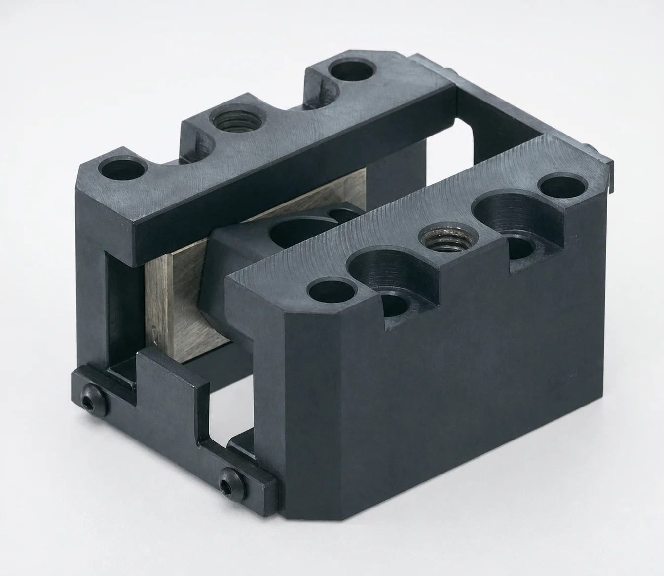
SCZN Oil-Free Slide Units for Loose Core
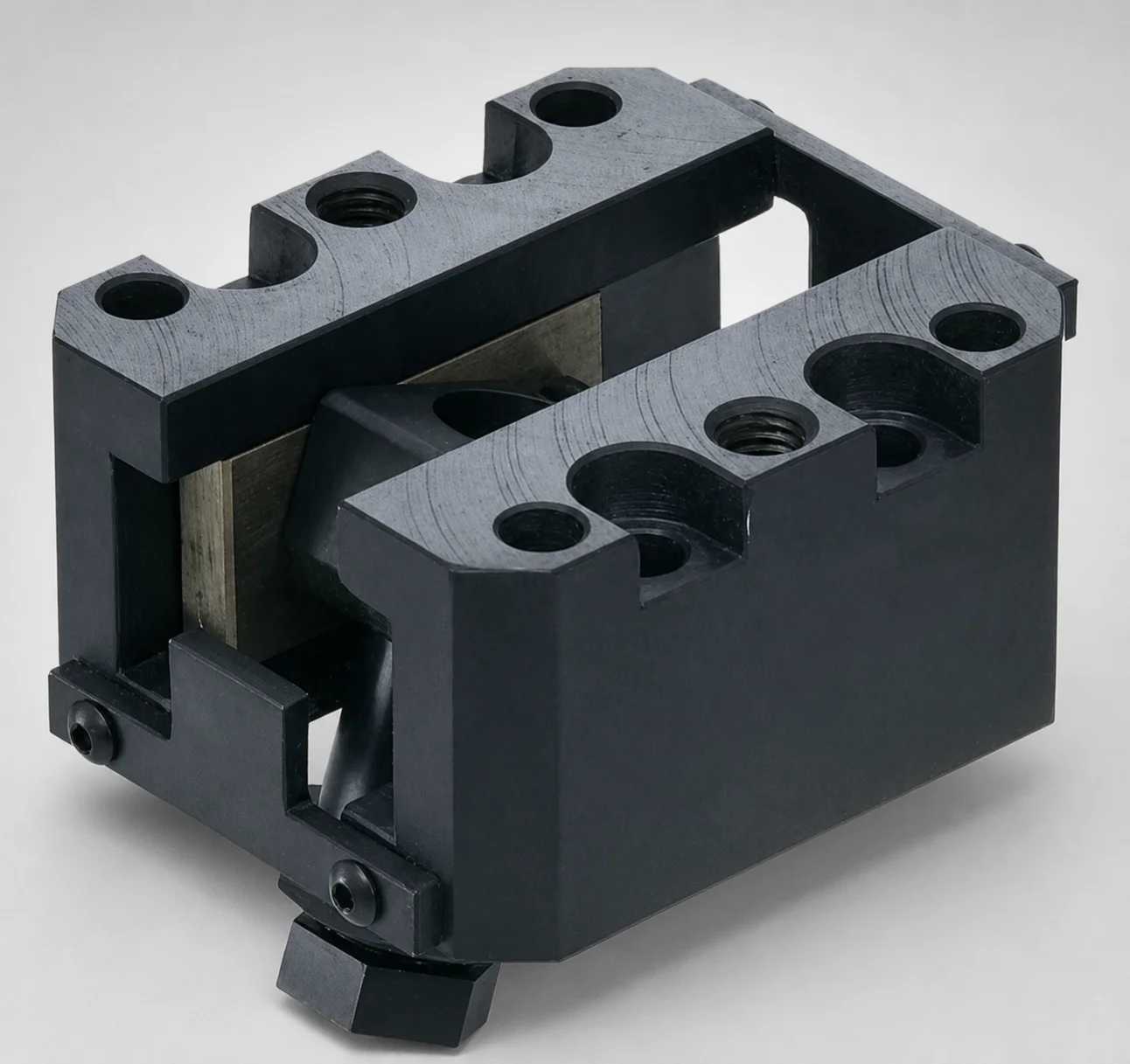
SCZA Oil-Free Slide Units for Loose Core - Inclined Pin Height Fine Tuning
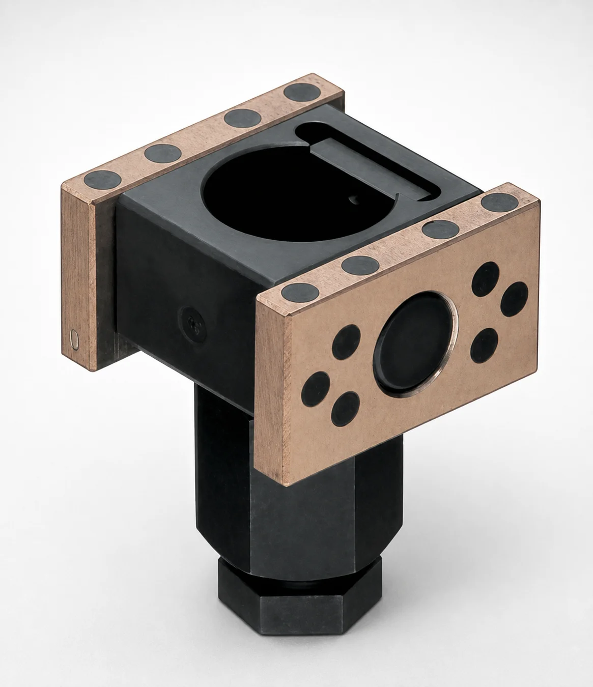
SCZAP Oil-Free Slide Inclined Pin Holders for Loose Core
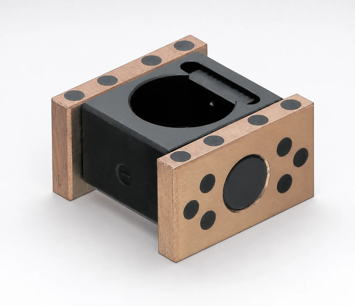
SCZNP Type Oil-Free Slide Inclined Pin Holders for Loose Core
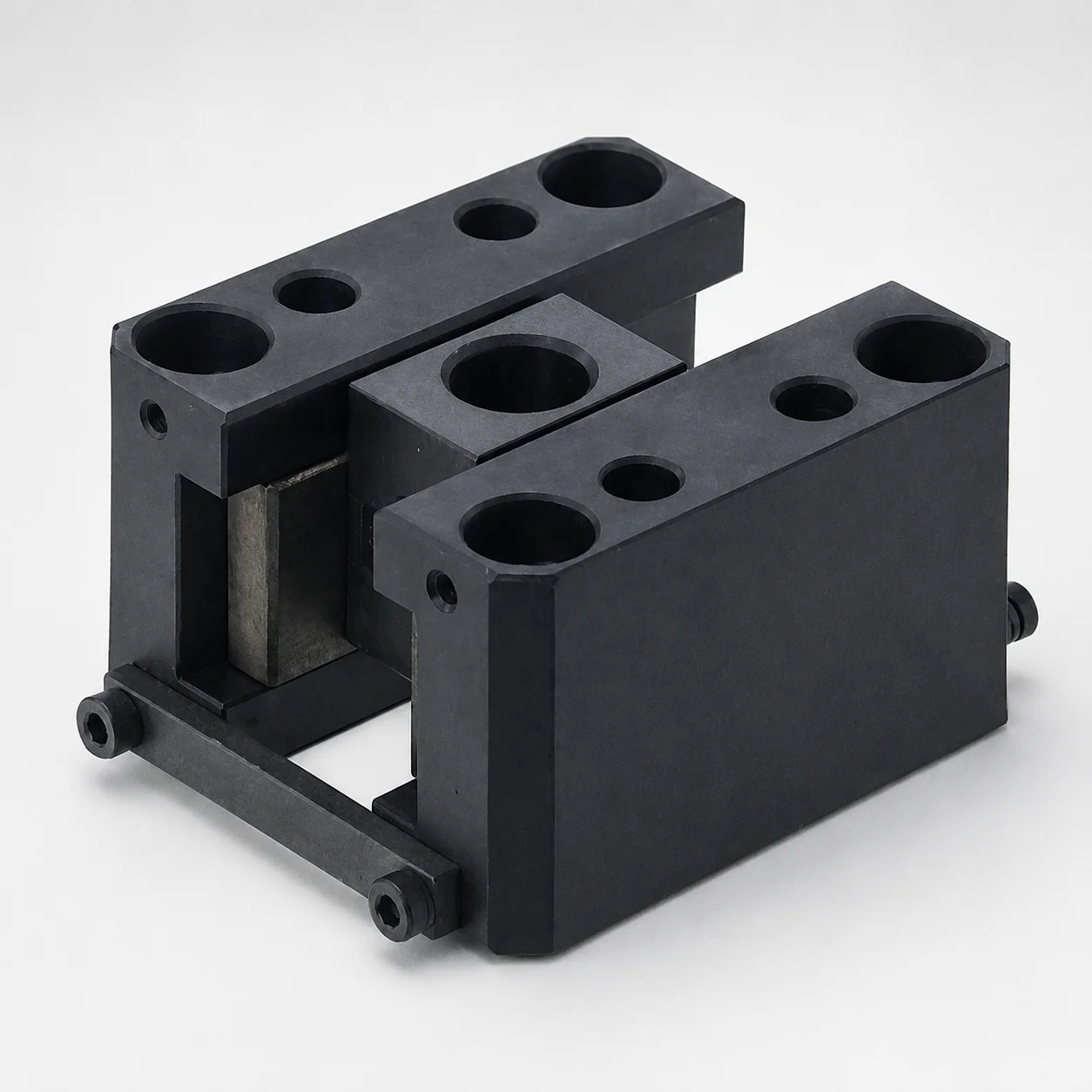
SCY Type Oil-Free Slide Units for Loose Core
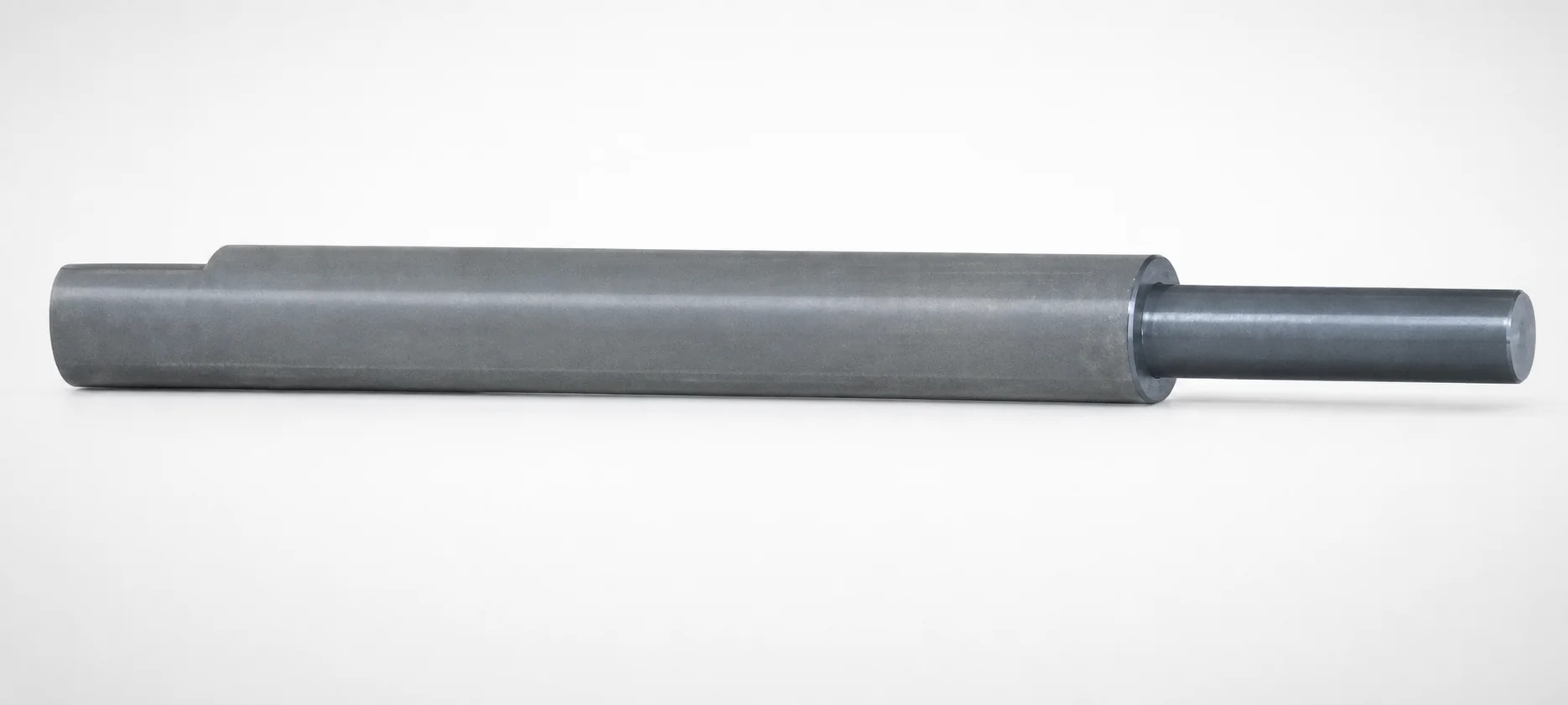
Inclined or Direct Push-Up Lifter Pins - Stepped
Need Custom Specifications?
Our engineering team can help with custom configurations, material selection, and volume pricing.