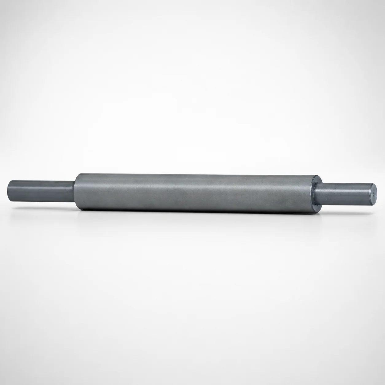
Inclined Direct Push-Up Lifter Pins - Both Ends Stepped
Inclined Direct Push-Up Lifter Pins - Both Ends Stepped (K-KSPSD) are designed for controlled lifter action in inclined direct push-up mechanisms. The stepped geometry supports reliable engagement and smooth motion under press cycle loads.
- Both-ends stepped lifter design improves locating stability for repeatable lift
- Compact tap size K-KSPSD fits typical assembly interfaces in lifter systems
- Optimized for inclined pin setups with slide unit side bearing engagement
- Suitable for tool sets requiring inclined direct push-up lifter pin integration
Specifications
3 configurations available
| D (Applicable inclined pin diameter) (mm) | L (L dimension) (mm) | F (Length of inclined block side bearing bore length) (mm) | P (Inclined block side shaft diameter) (mm) | V (Slide unit side diameter) (mm) | Y (Slide unit side length) (mm) | type |
|---|---|---|---|---|---|---|
| 16 | 100 ~ 800 | 10 ~ 40 | 8 ~ 13 | 12 ~ 14 | 12 ~ 56 | - |
| 20 | 100 ~ 800 | 10 ~ 68 | 10 ~ 17 | 15 ~ 18 | 15 ~ 72 | - |
| 30 | 100 ~ 800 | 10 ~ 50 | 15 ~ 27 | 20 ~ 27 | 20 ~ 108 | - |
Product Guide
Application Scenarios+
These inclined direct push-up lifter pins with stepped ends are used in injection molds that require controlled upward motion from an inclined lift mechanism, typically within slide cores and loose core layouts. The stepped geometry at both ends improves locating stability, which helps maintain repeatable lift height and timing under production press cycles.
- Automotive and appliance housings: suited for inclined lifter sections where the slide unit side bearing interface must stay aligned during actuation.
- Electronics connectors and interior parts: the direct push-up design supports stable engagement when the mold needs compact, precise lifter stroke for small-to-medium features.
- Multi-cavity tools with mixed lifter angles: available diameter options (D = 16/20/30 mm) help match core/inclined pin positioning without redesigning the lifter family.
Use this variant when your tool design benefits from stable end positioning and a compact tap-size mounting concept (K-KSPSD) in inclined direct push-up mechanisms.
Material & Process Details+
The provided dataset does not specify the steel grade, hardness (HRC), or heat-treatment state for this lifter pin series. Therefore, material-related claims such as “quenched and tempered” or exact HRC cannot be stated from the available information.
In general practice for inclined lifter pins, steels are selected to balance wear resistance against toughness to withstand sliding contact at the slide unit side and repeated impact from press cycles. Heat treatment typically targets hard surface performance while retaining core toughness to reduce the risk of chipping at stepped ends.
- If you need confirmation for quoting and qualification, request the material grade and heat treatment for series code 110200174140.
- When comparing alternatives, ensure the chosen variant provides comparable hardness and surface durability for the expected bearing-load and cycle count.
Sizing & Selection Guide+
Select dimensions by matching the inclined mechanism geometry and the slide unit side bearing interface. This series provides an applicable inclined pin diameter D = 16, 20, or 30 mm and a fixed overall length L = 100 to 800 mm.
- Inclined block side bearing bore length (F): choose within 10–40 mm, 10–68 mm, or 10–50 mm depending on your block design.
- Inclined block side shaft diameter (P): select from 8–13, 10–17, or 15–27 mm to fit the block-side bore/shaft interface.
- Slide unit side diameter (V) and length (Y): use V = 12–14, 15–18, or 20–27 mm and Y = 12–56, 15–72, or 20–108 mm to align the bearing contact area.
Because tolerances and fit classes are not specified in the input data, validate clearance/fit for step engagement and bearing seating with your supplier drawings to ensure smooth motion and stable lift.
Frequently Asked Questions
How do I choose the correct inclined pin diameter (D) for an inclined direct push-up lifter pin assembly?+
What does L = 100–800 mm control, and how should I set it relative to core stroke length?+
How do I select the bearing bore length (F) and slide unit side length (Y) to ensure stable lift engagement?+
What compatibility constraints exist between P (block side shaft diameter) and V (slide unit side diameter)?+
Does the both-ends stepped geometry affect how I design the installation location in a slide core system?+
Related Products
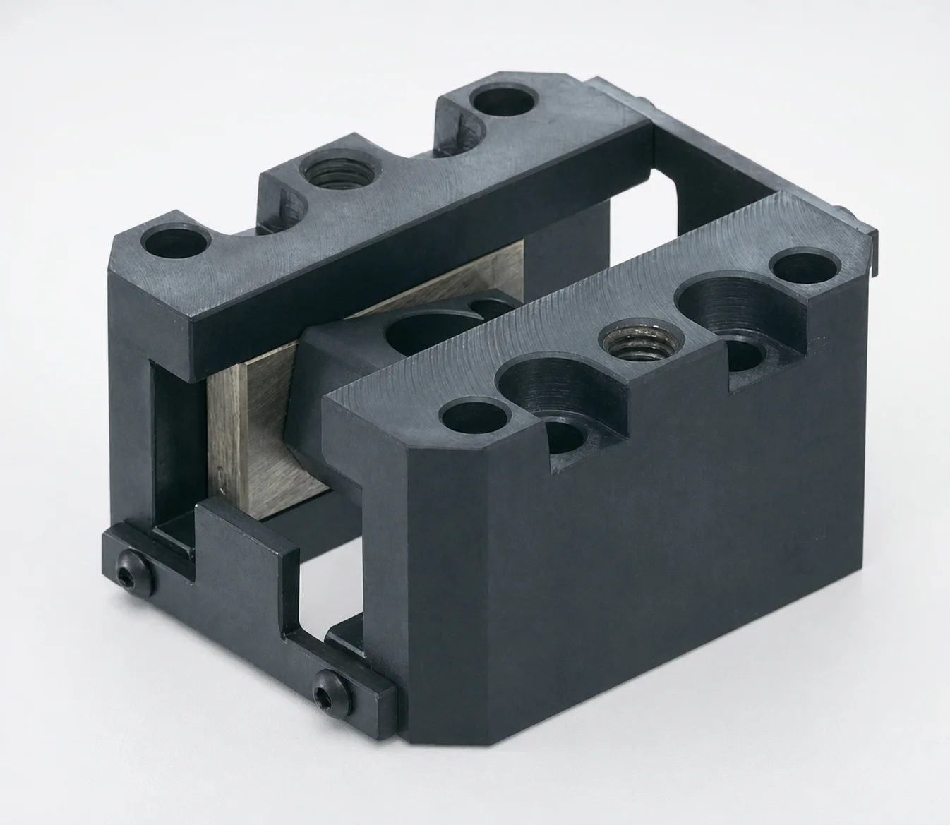
SCZN Oil-Free Slide Units for Loose Core
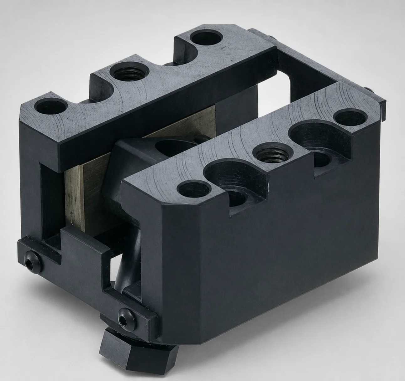
SCZA Oil-Free Slide Units for Loose Core - Inclined Pin Height Fine Tuning
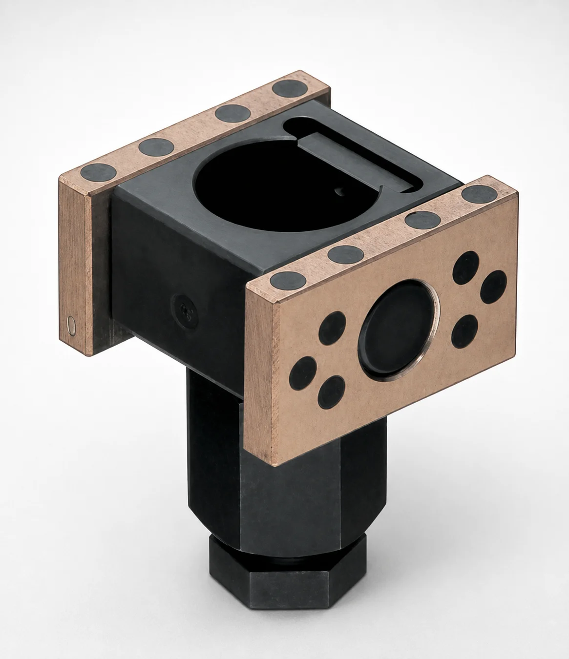
SCZAP Oil-Free Slide Inclined Pin Holders for Loose Core
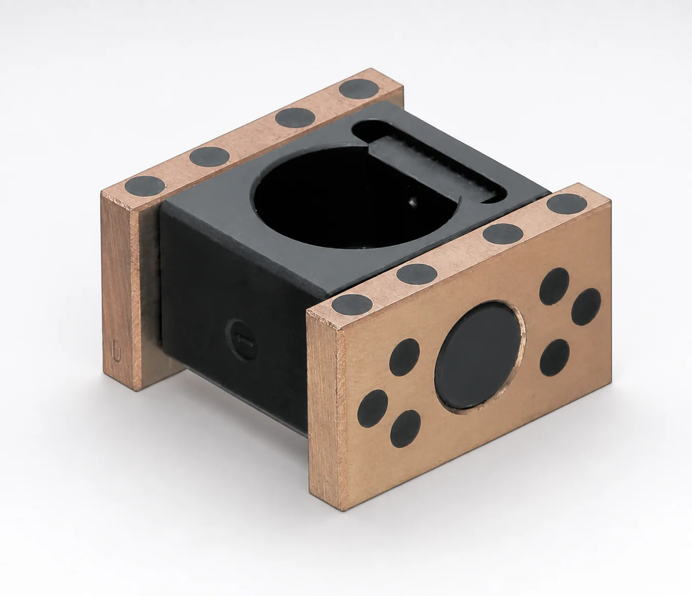
SCZNP Type Oil-Free Slide Inclined Pin Holders for Loose Core
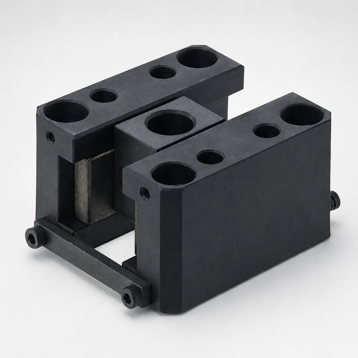
SCY Type Oil-Free Slide Units for Loose Core
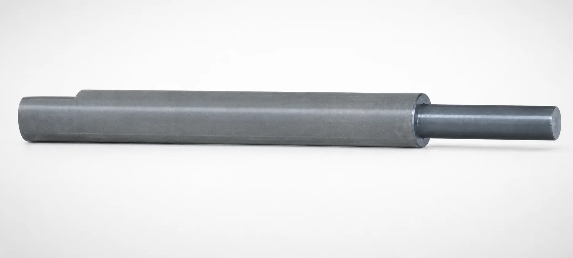
Inclined or Direct Push-Up Lifter Pins - Stepped
Need Custom Specifications?
Our engineering team can help with custom configurations, material selection, and volume pricing.