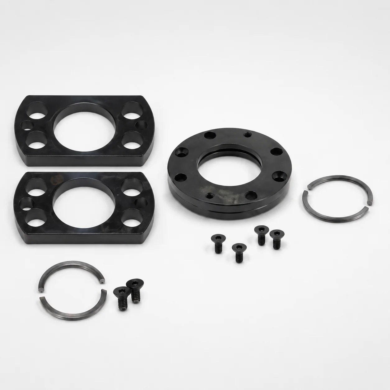
Upper Groove Mount Gas Spring Brackets (FC)
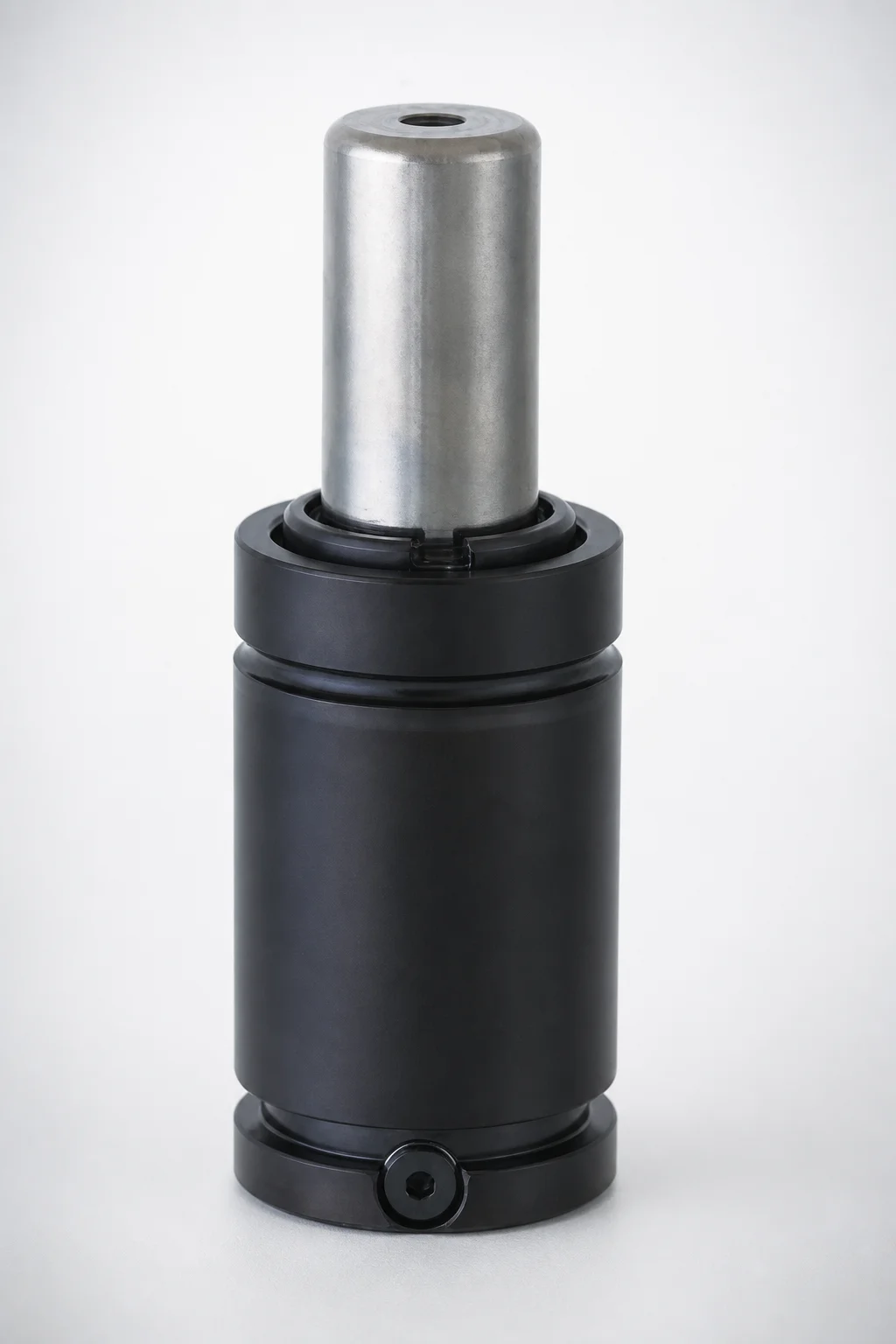
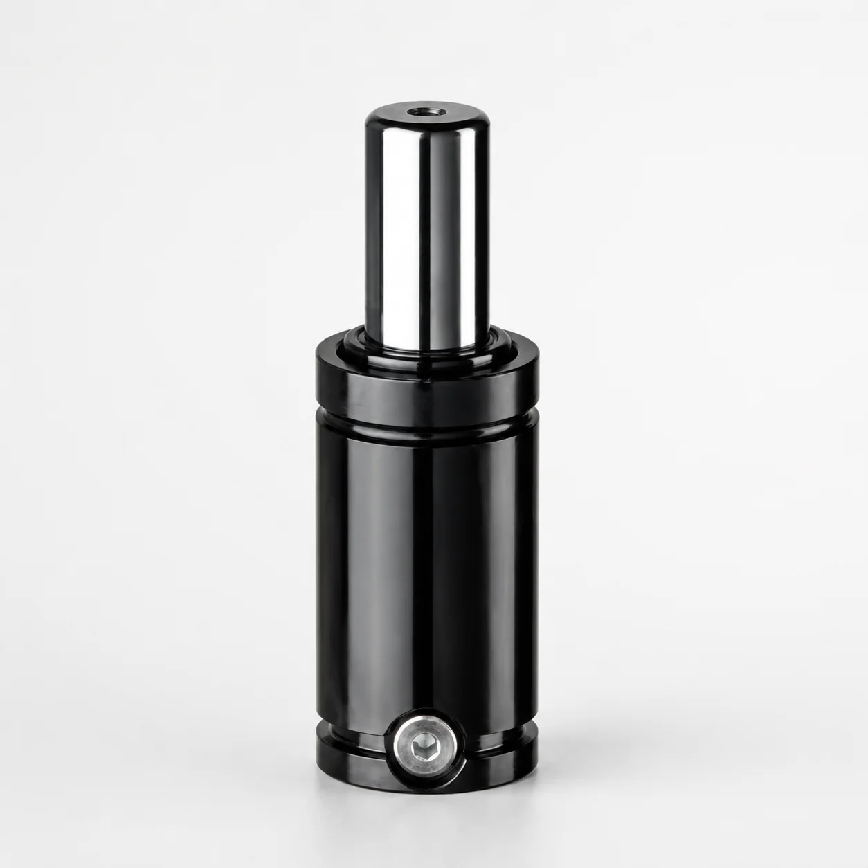
Upper Groove Mount gas spring brackets (FC) are mounting plates designed to be fixed in the upper groove of the gas spring body, improving installation stability and alignment during assembly. Built for repeatable positioning across multi-type layouts.
- Mounting plate locks into the upper groove of the gas spring body
- Compatible for upper-groove mounting with secure, consistent fit
- Supports selected plate types (FC/FCC) for different design requirements
- Commonly used in industrial cabinets, lifting systems, and support mechanisms
Specifications
4 configurations available
| Outer diameter (D) (mm) | Plate Type | type |
|---|---|---|
| 25 | FC | - |
| 45 | FC | - |
| 50 | FC | - |
| 19 | FCC | - |
Product Guide
Application Scenarios+
Upper groove mount gas spring brackets (FC) are used in injection-molded and fabricated assemblies where the gas spring must remain precisely aligned during repeated installation cycles. The mounting plate engages the upper groove of the gas spring body, helping maintain consistent stroke-direction positioning and reducing misalignment in downstream linkages.
- Industrial cabinet and enclosure supports: The bracket’s upper-groove lock supports stable door/lid opening angles, especially when cabinet layouts require repeatable plate placement across multiple units.
- Lifting systems and hinges: For mechanism housings that experience frequent actuation, the secure upper-groove interface provides consistent bracket orientation to the gas spring body.
- Mixed design BOMs: Selecting FC vs FCC plate types helps match differing mounting requirements while keeping the same upper-groove mounting principle.
The available outer diameter options (D = 19, 25, 45, 50 mm) allow engineers to select the bracket size that best matches the gas spring groove geometry and assembly envelope.
Material & Process Details+
The provided product data specifies the bracket configuration (FC/FCC) and the mounting interface dimensions, but it does not list a steel grade, heat-treatment condition, or hardness (HRC). Therefore, the material-specific properties (wear resistance, toughness trade-offs, and any nitriding/quenching & tempering) cannot be stated from the current dataset.
For engineering qualification, confirm the supplier’s material specification for the bracket’s plate and any spring-related interface parts. When selecting between FC and FCC plate types, evaluate how the plate design impacts stiffness and load distribution; this is often more influential than microstructural differences when the mounting is controlled by the upper groove.
- Confirm steel grade & hardness: Request the heat-treatment state (e.g., pre-hardened vs. quenched & tempered) and target HRC from incoming inspection documentation.
- Wear and fatigue considerations: Verify corrosion resistance and surface treatment if the application uses frequent cycling or exposure to moisture.
Sizing & Selection Guide+
To select the correct bracket, match the outer diameter (D) of the bracket to the gas spring body’s upper groove geometry and your available mounting envelope. The available D values are 19, 25, 45, and 50 mm, and selecting the correct D is essential for a secure upper-groove fit.
- Step 1 — Determine the required D: Use the gas spring upper groove design (or part drawings) to identify which bracket D will seat correctly without interference.
- Step 2 — Choose plate type: Select FC or FCC based on your layout and the required plate design variant.
- Step 3 — Check assembly tolerance stack-up: Ensure your tolerances for groove seating, fastener clearances (if used in your system), and housing wall thickness allow full engagement of the mounting plate.
- Step 4 — Verify fit under actuation: Confirm that deflection during cycling will not cause partial disengagement; a proper groove lock is critical.
Dimensions shown are configurable via D selection and plate type; no additional size ranges (e.g., length/width) were provided in the current data.
Frequently Asked Questions
Which outer diameter (D) should I use for upper-groove seating on the gas spring body?+
The bracket provides specific outer diameter (D) options: 19, 25, 45, and 50 mm. Select the D that matches the gas spring’s upper groove geometry so the mounting plate can fully lock into the groove without interference.
If you are unsure, compare against the gas spring groove dimensions from the OEM drawing to prevent partial engagement and misalignment.
What is the difference between plate types FC and FCC for this upper groove mounting bracket?+
This product is offered in plate types FC and FCC. While the dataset confirms that these are compatible with the upper-groove mounting concept, it does not provide internal geometry or thickness differences.
To choose correctly, validate against your mechanism layout and any drawings specifying the required plate variant for fit and stiffness.
Does the upper groove mounting design help reduce misalignment during repeated assembly?+
Yes. The bracket is designed so the mounting plate locks into the upper groove of the gas spring body, promoting secure alignment and repeatable positioning.
This is particularly relevant for installations like cabinet/lid supports or lifting mechanisms where the gas spring is actuated frequently.
Are there material/heat-treatment specs (steel grade, HRC) available for qualification?+
The provided data does not include a steel grade, heat treatment state, or hardness (HRC).
For mechanical qualification, request the material certification (including heat-treatment condition and hardness) and confirm surface treatment/corrosion requirements for your duty cycle.
What tolerance and fit checks should I perform for the upper-groove lock?+
Because the bracket’s functional fit depends on the upper groove engagement, check tolerance stack-up between the gas spring groove and the mounting interface in your enclosure or housing.
Use the selected D value (19/25/45/50 mm) and confirm clearance for any surrounding walls and fastener features so the plate can fully seat and remain locked under actuation.
Related Products
Need Custom Specifications?
Our engineering team can help with custom configurations, material selection, and volume pricing.