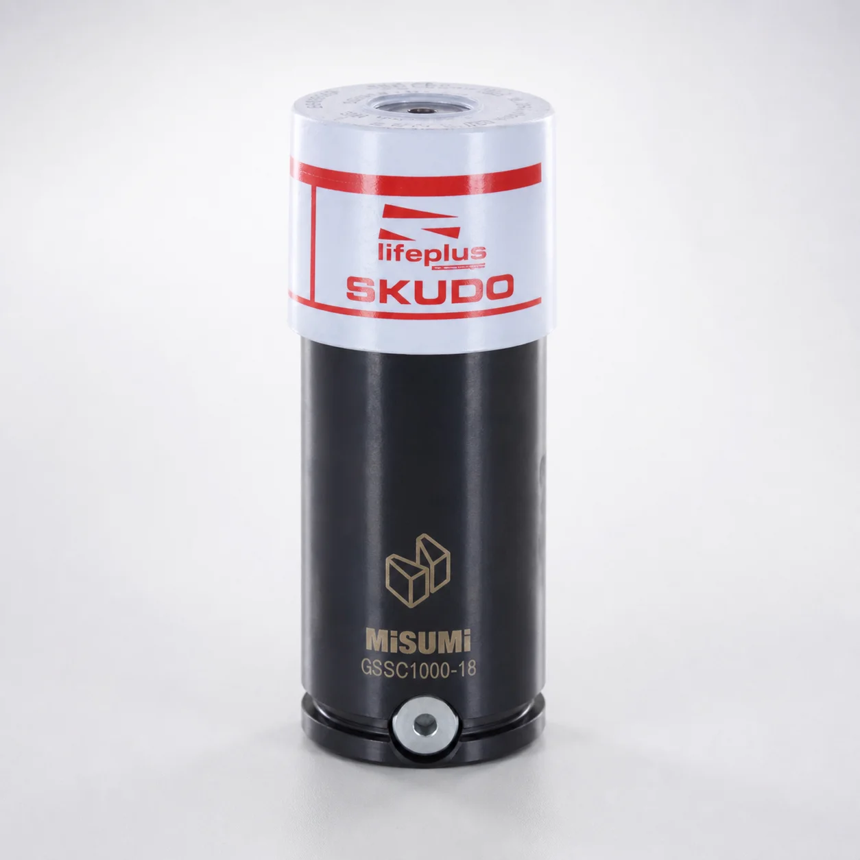
GSSC Series Gas Springs High Initial Load
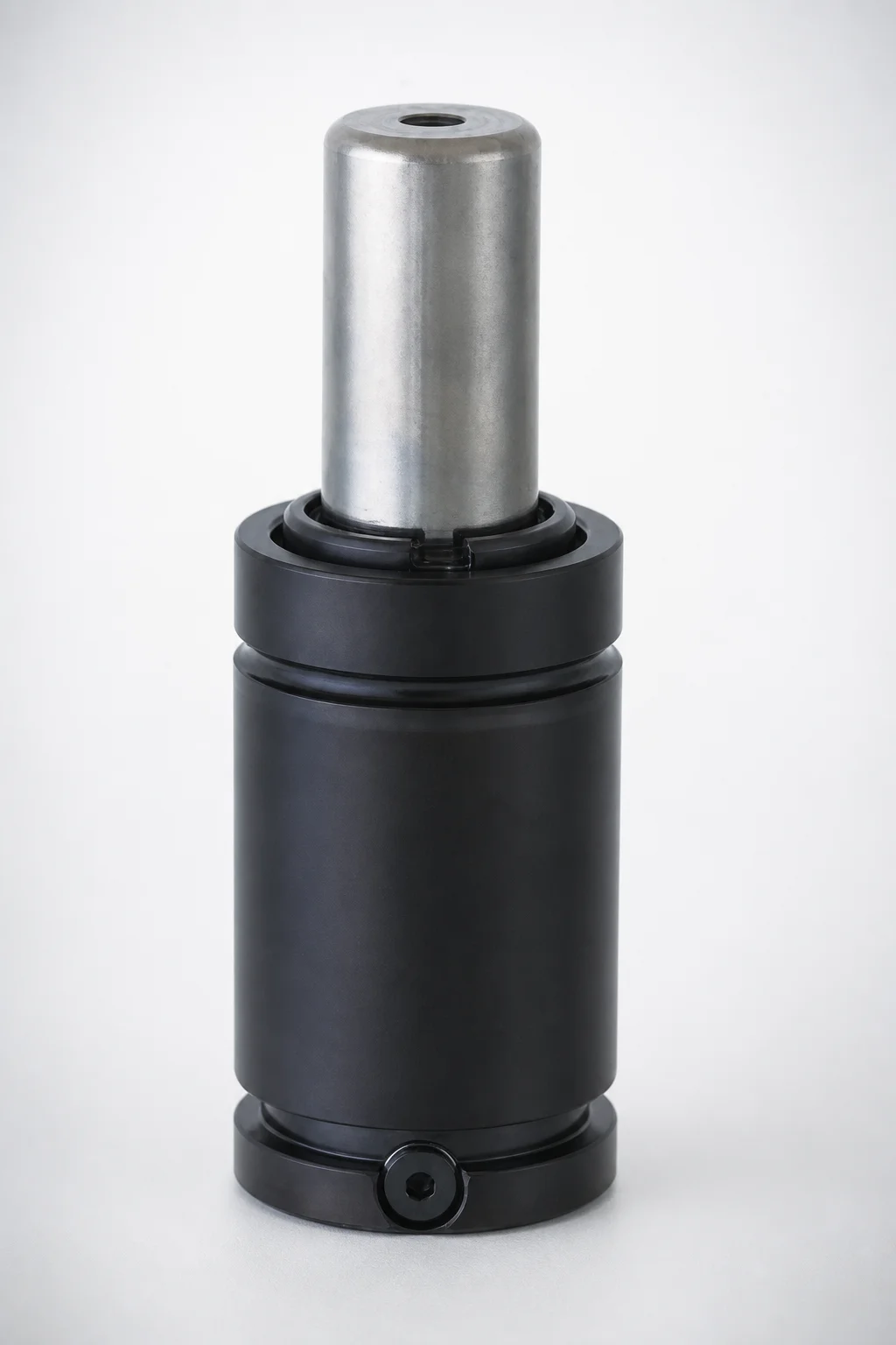
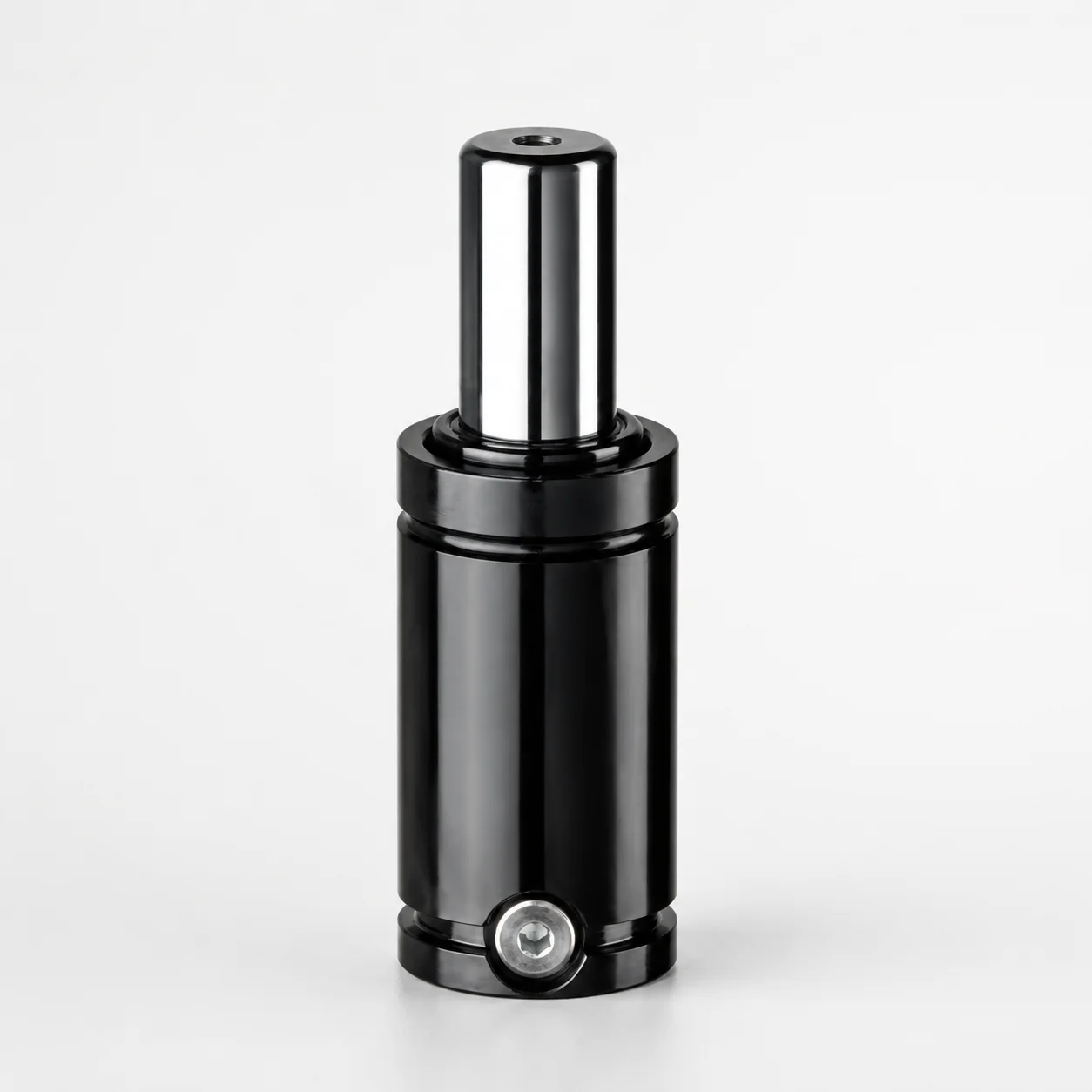
GSSC Series gas springs high initial load deliver heavy-duty support for piping applications, featuring an oil cover to improve damping stability and smooth movement under demanding industrial duty. Built for consistent operation, they help reduce vibration and maintain controlled travel.
- Oil-covered heavy-duty gas spring body designed for piping systems and stable force output
- Supports gas venting with hose linkage options to match exhaust routing requirements
- High initial load range supports controlled motion across varying operating conditions
- Type GSSC suited to robust assembly designs and long-cycle use in mechanical equipment
Specifications
114 configurations available
| Outer diameter (D) (mm) | Stroke (S) (mm) | L Dimension (L) (mm) | Initial load (N) | Gas Venting With Hose Linkage | type |
|---|---|---|---|---|---|
| 38 | 6 | 61 | 10600 | No | - |
| 38 | 6 | 61 | 10600 | Yes | - |
| 38 | 10 | 78 | 10600 | No | - |
| 38 | 10 | 78 | 10600 | Yes | - |
| 38 | 16 | 100 | 10600 | No | - |
| 38 | 16 | 100 | 10600 | Yes | - |
| 38 | 25 | 135 | 10600 | No | - |
| 38 | 25 | 135 | 10600 | Yes | - |
| 38 | 32 | 167 | 10600 | No | - |
| 38 | 32 | 167 | 10600 | Yes | - |
| 38 | 40 | 195 | 10600 | No | - |
| 38 | 40 | 195 | 10600 | Yes | - |
| 38 | 50 | 230 | 10600 | No | - |
| 38 | 50 | 230 | 10600 | Yes | - |
| 120 | 10 | 100 | 117800 | No | - |
| 120 | 10 | 100 | 117800 | Yes | - |
| 120 | 16 | 126 | 117800 | No | - |
| 120 | 16 | 126 | 117800 | Yes | - |
| 120 | 25 | 155 | 117800 | No | - |
| 120 | 25 | 155 | 117800 | Yes | - |
| 120 | 32 | 187 | 117800 | No | - |
| 120 | 32 | 187 | 117800 | Yes | - |
| 120 | 40 | 220 | 117800 | No | - |
| 120 | 40 | 220 | 117800 | Yes | - |
| 120 | 50 | 260 | 117800 | No | - |
| 120 | 50 | 260 | 117800 | Yes | - |
| 50 | 6 | 66 | 18850 | No | - |
| 50 | 6 | 66 | 18850 | Yes | - |
| 50 | 10 | 80 | 18850 | No | - |
| 50 | 10 | 80 | 18850 | Yes | - |
| 50 | 16 | 106 | 18850 | No | - |
| 50 | 16 | 106 | 18850 | Yes | - |
| 50 | 25 | 135 | 18850 | No | - |
| 50 | 25 | 135 | 18850 | Yes | - |
| 50 | 32 | 162 | 18850 | No | - |
| 50 | 32 | 162 | 18850 | Yes | - |
| 50 | 40 | 190 | 18850 | No | - |
| 50 | 40 | 190 | 18850 | Yes | - |
| 50 | 50 | 220 | 18850 | No | - |
| 50 | 50 | 220 | 18850 | Yes | - |
| 150 | 10 | 110 | 184100 | No | - |
| 150 | 10 | 110 | 184100 | Yes | - |
| 150 | 16 | 136 | 184100 | No | - |
| 150 | 16 | 136 | 184100 | Yes | - |
| 150 | 25 | 165 | 184100 | No | - |
| 150 | 25 | 165 | 184100 | Yes | - |
| 150 | 32 | 197 | 184100 | No | - |
| 150 | 32 | 197 | 184100 | Yes | - |
| 150 | 40 | 235 | 184100 | No | - |
| 150 | 40 | 235 | 184100 | Yes | - |
Product Guide
Application Scenarios+
These high-initial-load gas springs are used in injection mold tooling wherever controlled vertical or lifting motion is needed, especially for large or heavy assemblies exposed to vibration. In molding cell systems, the oil-covered construction helps damp oscillation so fixtures, guards, or moving access covers travel more smoothly through the cycle.
For industrial piping support and positioning, the stable force output across the available stroke range (6–50 mm) helps maintain consistent support under varying operating conditions. The variant is suited to duty where repeatable motion and reduced chatter are critical.
Where exhaust routing or vent control matters, the gas venting with hose linkage option (available as “Yes”) allows connection to external hoses, supporting cleaner integration into machine layouts and improving system consistency.
- Heated or vibration-prone mold platforms: oil cover improves damping stability and smooth movement.
- Heavy fixtures for piping-related equipment: high initial load supports controlled travel.
- Vent-managed installations: hose-linked venting available to match exhaust routing requirements.
Material & Process Details+
This product is an oil-covered gas spring assembly designed to deliver stable force with damping. While the provided specifications focus on force and geometry, the oil cover is the key functional “material feature” that improves motion smoothness by reducing vibration and stabilizing the motion profile under industrial duty.
Key performance trade-offs typically associated with oil-covered gas springs are improved damping versus slightly more system complexity (oil management and venting). For applications requiring predictable support force, the high initial load range (4250–184100 N) helps balance the spring’s overall force behavior across the stroke.
- Oil-covered construction: enhanced damping stability and smoother movement.
- Initial load performance: supports controlled travel in demanding cycles.
- Venting integration: hose linkage option (“Yes”) supports system-level routing needs.
Note: no specific steel grade, HRC hardness, or heat-treatment state is provided in the input data, so they cannot be stated reliably for this listing.
Sizing & Selection Guide+
Selection starts by matching the gas spring’s outer diameter D and package length L to the available space in your mold tooling fixture. Choose D = 25–150 mm and L = 61–270 mm so the cylinder can be mounted without interference through full travel.
Next, match stroke S = 6–50 mm to the required deflection or travel of the moving component (covers, clamps, lifting jigs). Then set the required initial load from 4250–184100 N to ensure the supported assembly maintains controlled motion at the start of travel.
- Geometry fit: confirm mounting clearance using D and L across the stroke path.
- Travel matching: ensure S covers the full intended motion in the cycle.
- Force matching: size initial load to counteract weight/friction at the beginning of stroke.
- Venting: select gas venting “No” vs “Yes” depending on whether hose linkage is required.
Tolerance/fit: the provided data lists only dimension ranges, not tolerance values. Verify your manufacturer drawing for mounting interface tolerances before final design freeze.
Frequently Asked Questions
How do I choose the correct gas spring stroke (S = 6–50 mm) for a moving mold fixture or access cover?+
What initial load (4250–184100 N) should be targeted when supporting heavy piping-related equipment in an industrial system?+
When should I select gas venting with hose linkage (Yes vs No) for machine integration?+
How do I ensure the gas spring cylinder fits within the available mounting space using D (25–150 mm) and L (61–270 mm)?+
Does the oil-covered construction change force stability for high-cycle industrial duty compared with non-oil-covered options?+
Related Products
Need Custom Specifications?
Our engineering team can help with custom configurations, material selection, and volume pricing.