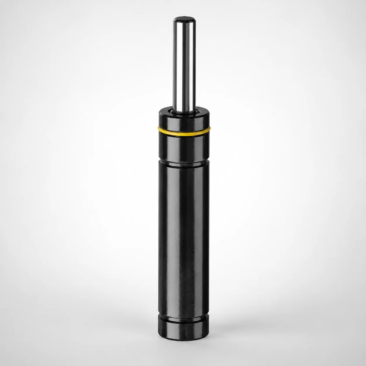
GSU Series Selective Charging Pressure Gas Springs
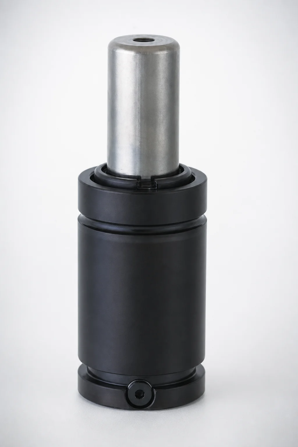
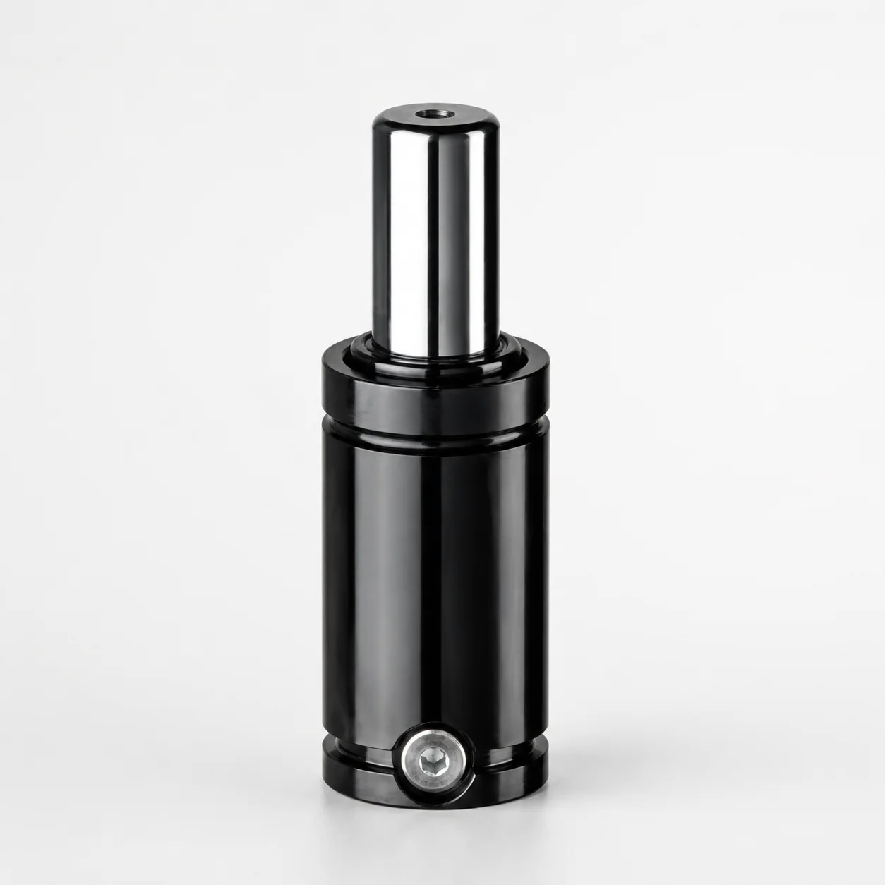
GSU Series selective charging pressure gas springs are designed as a small-diameter solution for link system applications. The same size and stroke support different selectable loads, helping engineers match motion requirements without changing the core form factor.
- Small-diameter format suitable for link systems and compact mechanisms
- Use selective charging pressure to select different loads per size and stroke
- GSU type construction delivers consistent performance for controlled motion
- Supports a wide operating range across selectable stroke and initial load needs
Specifications
280 configurations available
| Outer diameter (D) (mm) | Stroke (S) (mm) | L Dimension (L) (mm) | Initial load (N) | type |
|---|---|---|---|---|
| 12 | 7 | 56 | 250 | - |
| 12 | 7 | 56 | 130 | - |
| 12 | 7 | 56 | 380 | - |
| 12 | 7 | 56 | 500 | - |
| 12 | 10 | 62 | 250 | - |
| 12 | 10 | 62 | 130 | - |
| 12 | 10 | 62 | 380 | - |
| 12 | 10 | 62 | 500 | - |
| 12 | 12.7 | 67.4 | 250 | - |
| 12 | 12.7 | 67.4 | 130 | - |
| 12 | 12.7 | 67.4 | 380 | - |
| 12 | 12.7 | 67.4 | 500 | - |
| 12 | 15 | 72 | 250 | - |
| 12 | 15 | 72 | 130 | - |
| 12 | 15 | 72 | 380 | - |
| 12 | 15 | 72 | 500 | - |
| 12 | 19 | 80 | 250 | - |
| 12 | 19 | 80 | 130 | - |
| 12 | 19 | 80 | 380 | - |
| 12 | 19 | 80 | 500 | - |
| 12 | 25 | 92 | 250 | - |
| 12 | 25 | 92 | 130 | - |
| 12 | 25 | 92 | 380 | - |
| 12 | 25 | 92 | 500 | - |
| 12 | 38 | 118 | 250 | - |
| 12 | 38 | 118 | 130 | - |
| 12 | 38 | 118 | 380 | - |
| 12 | 38 | 118 | 500 | - |
| 12 | 50 | 142 | 250 | - |
| 12 | 50 | 142 | 130 | - |
| 12 | 50 | 142 | 380 | - |
| 12 | 50 | 142 | 500 | - |
| 12 | 63.5 | 172 | 250 | - |
| 12 | 63.5 | 172 | 130 | - |
| 12 | 63.5 | 172 | 380 | - |
| 12 | 63.5 | 172 | 500 | - |
| 12 | 75 | 195 | 250 | - |
| 12 | 75 | 195 | 130 | - |
| 12 | 75 | 195 | 380 | - |
| 12 | 75 | 195 | 500 | - |
| 12 | 80 | 205 | 250 | - |
| 12 | 80 | 205 | 130 | - |
| 12 | 80 | 205 | 380 | - |
| 12 | 80 | 205 | 500 | - |
| 12 | 100 | 245 | 250 | - |
| 12 | 100 | 245 | 130 | - |
| 12 | 100 | 245 | 380 | - |
| 12 | 100 | 245 | 500 | - |
| 12 | 125 | 295 | 250 | - |
| 12 | 125 | 295 | 130 | - |
Product Guide
Application Scenarios+
Selective charging pressure gas springs are used inside compact link systems where space is limited but motion repeatability is critical. Their small-diameter formats (D as low as 12 mm) make them well suited for mechanisms that must fit within tight mold tool housings, slides, or linkage frames without increasing the overall envelope.
In automation and indexing tooling, engineers often need different assisting forces for the same stroke to compensate for part weight changes or different linkage leverage ratios. This variant supports selective charging, enabling multiple initial load levels within the same size and stroke family to reduce redesign effort.
For in-press assist devices and controlled open/close motions, the defined stroke window and consistent gas-spring behavior help maintain a stable force curve across cycles. The available stroke range (S = 7–125 mm) and broad load selection (50–3200 N) allow engineers to tune performance while keeping the same component form factor.
Material & Process Details+
This product is specified as a gas-spring component rather than a machined steel tool insert, so no steel grade, hardness (HRC), or heat-treatment condition is provided in the available data. As such, the load-setting capability is achieved by selective charging pressure rather than by metallurgical modification.
From a manufacturing perspective, the key process distinction is that the spring is produced to a defined stroke and is then delivered with an initial load corresponding to the selected charging pressure. The component must be built to maintain seal integrity and stable internal pressure over the specified stroke range.
- Heat treatment: Not specified (selective charging is the primary tuning method).
- Hardness/wear resistance: Not specified because no steel grade or surface hardness data is given.
- Material comparison: Not possible with the provided information; this page focuses on configuration (D, S, and initial load).
Sizing & Selection Guide+
Start by matching the required space envelope to the available outer diameter options: D = 12, 15, 19, 25, or 32 mm. Choose the diameter that fits the linkage layout and mounting clearances while preserving tool structure around the mechanism.
Next, select the stroke length from S = 7 to 125 mm. Your stroke should align with the intended opening/closing travel of the linked mechanism; using the correct stroke range reduces over-travel stress and improves force repeatability.
Then tune the initial load to your motion requirement: 50 to 3200 N. Because this family supports selectable loads within the same size and stroke, you can keep the same form factor while adjusting the assistance force.
- Overall length (L): available across L = 56 to 295 mm; confirm L compatibility with mounting geometry.
- Tolerances/fit: no tolerance values are provided in the data, so verify fit using your linkage clearances and end-connection interface requirements.
Frequently Asked Questions
How do I select the correct outer diameter (D) for a compact link mechanism using the GSU selective charging family?+
Choose the smallest feasible option from the available outer diameters: D = 12, 15, 19, 25, or 32 mm. Validate that the selected diameter clears adjacent tooling members while maintaining the designed linkage leverage.
Because this series offers selectable loads within the same size and stroke family, diameter selection can focus on packaging first.
What stroke range (S) can be specified, and how do I match it to my required open/close travel?+
The available stroke is S = 7 to 125 mm. Match S to the effective travel in your linkage design to avoid forcing the mechanism beyond its intended motion window.
If your motion requirement changes, keep the same size family and select an appropriate initial load where possible.
How does selective charging pressure help when I need different assisting forces without changing the core form factor?+
This GSU family is described as providing selectable loads within the same size and stroke. Instead of changing the component form, you can request a configuration with the required initial load (50–3200 N) for your application.
This is especially useful when linkage geometry or part mass varies across programs.
What L (overall dimension) should I verify to ensure the spring fits my mounting layout?+
Confirm the available overall length range: L = 56 to 295 mm. Your selected L must fit the tool’s mounting points and allow full stroke movement without interference.
Since tolerances are not provided in the dataset, use your linkage’s mechanical clearances to verify fit.
Can I compare material hardness or heat-treatment options for this gas spring series to optimize wear?+
The provided product data does not list a steel grade, hardness (HRC), or heat-treatment state. The load tuning is performed via selective charging pressure, not through specified metallurgical heat treatment.
For wear or durability assumptions, rely on the manufacturer configuration and your own duty-cycle validation rather than hardness-based selection from this dataset.
Related Products
Need Custom Specifications?
Our engineering team can help with custom configurations, material selection, and volume pricing.