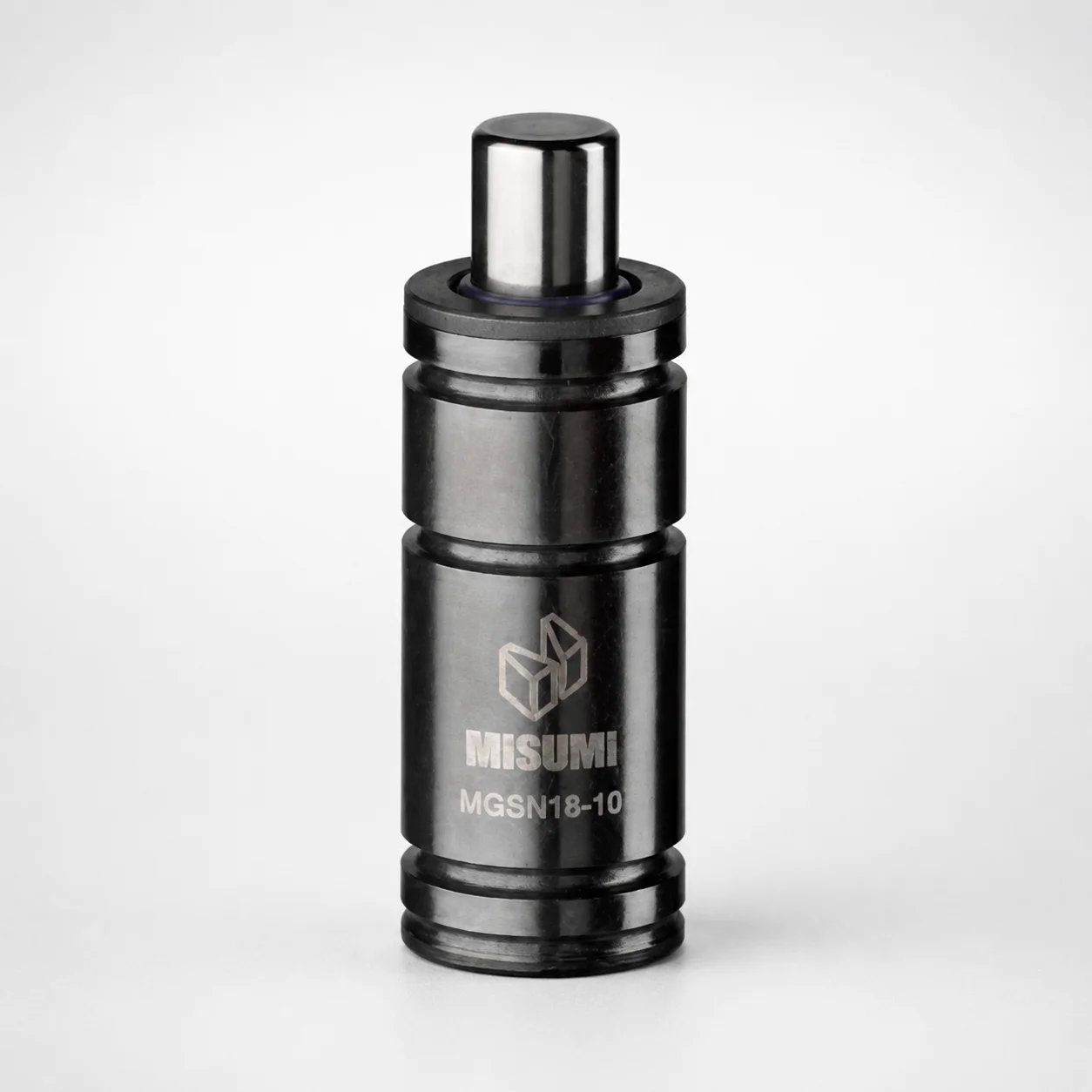
MGSN Series Heavy Load Mini Gas Springs
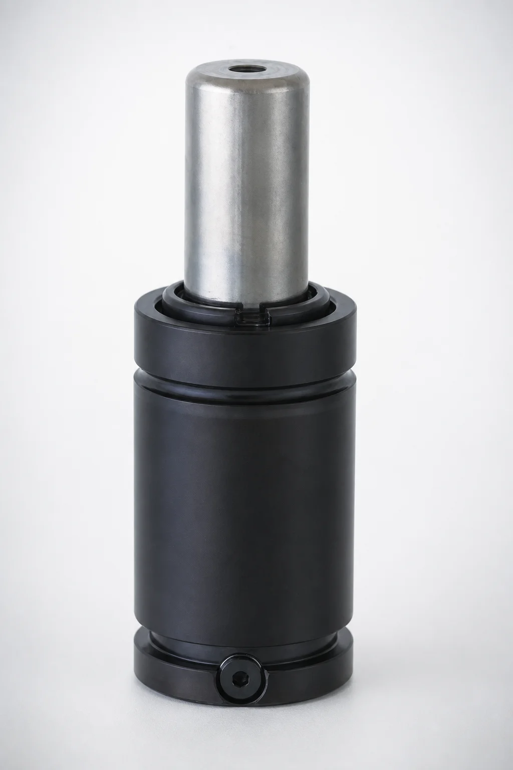
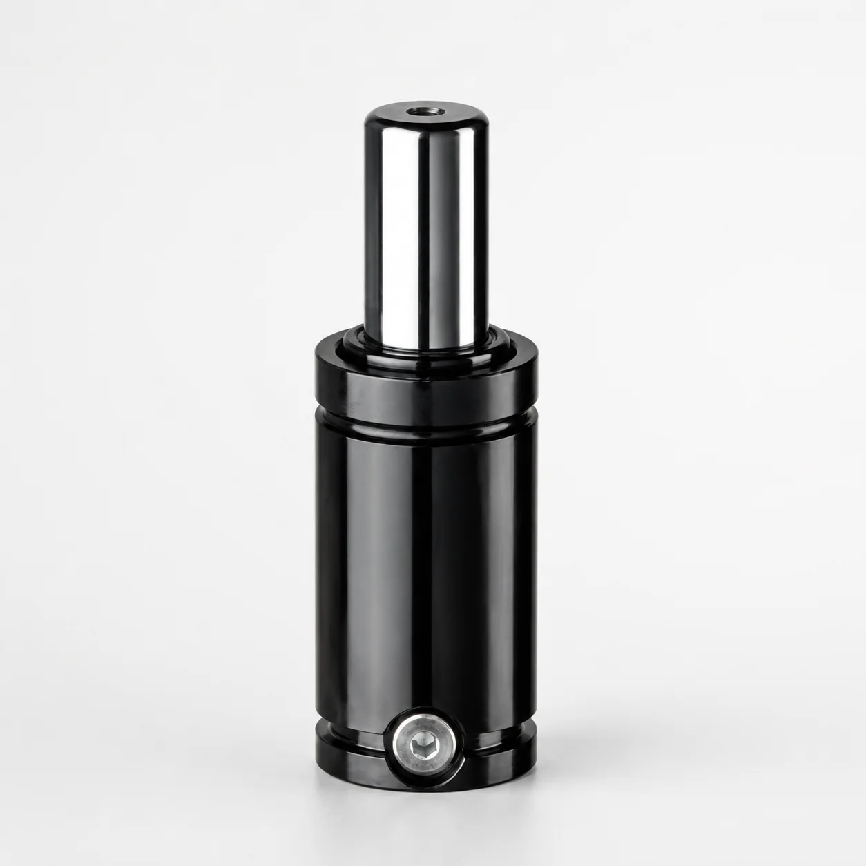
Gas springs MGSN series heavy load mini provide compact, high-support performance for machine covers and industrial assemblies. As the successor to MGSC, the MGSN type is designed for reliable operation under heavy initial load conditions.
- Heavy-load mini construction for stable positioning in constrained spaces
- Successor model to MGSC for smoother replacement in ongoing maintenance
- Robust loading capability from 1000 N to 5100 N for demanding applications
- Compact size options with selectable outer diameters support varied designs
Specifications
23 configurations available
| Outer diameter (D) (mm) | Stroke (S) (mm) | L Dimension (L) (mm) | Initial load (N) | type |
|---|---|---|---|---|
| 16 | 10 | 55 | 1000 | - |
| 16 | 15 | 65 | 1000 | - |
| 16 | 25 | 85 | 1000 | - |
| 16 | 38 | 111 | 1000 | - |
| 19 | 10 | 55 | 1700 | - |
| 19 | 15 | 65 | 1700 | - |
| 19 | 25 | 85 | 1700 | - |
| 19 | 38 | 111 | 1700 | - |
| 25 | 10 | 55 | 3600 | - |
| 25 | 15 | 65 | 3600 | - |
| 25 | 25 | 85 | 3600 | - |
| 25 | 38 | 111 | 3600 | - |
| 32 | 10 | 55 | 5100 | - |
| 32 | 15 | 65 | 5100 | - |
| 32 | 20 | 75 | 5100 | - |
| 32 | 25 | 85 | 5100 | - |
| 32 | 32 | 100 | 5100 | - |
| 32 | 38 | 111 | 5100 | - |
| 32 | 45 | 125 | 5100 | - |
| 32 | 50 | 135 | 5100 | - |
| 32 | 56 | 150 | 5100 | - |
| 32 | 63 | 165 | 5100 | - |
| 32 | 80 | 195 | 5100 | - |
Product Guide
Application Scenarios+
This heavy-load mini gas spring is used in injection mold tooling and industrial assemblies where compact, stable support is needed in tight spaces. Its 1000 N to 5100 N initial load makes it suitable for scenarios that require consistent opening force against gravity and friction.
- Automated equipment access doors and machine covers: Pair the spring with a linkage to maintain predictable cover position; the mini format and selectable outer diameters (16, 19, 25, 32 mm) help fit constrained mounting envelopes.
- Industrial tooling housings and guarding: The successor to MGSC concept supports straightforward replacement during maintenance while still providing heavy initial load behavior.
- Compact lift-and-hold mechanisms for fixtures: Use the selectable stroke (S) 10–80 mm to match lift travel, improving cycle stability when stops and seals create additional resistance.
Material & Process Details+
The provided product data focuses on performance parameters (initial load, stroke, and dimensions) and does not specify the internal gas-spring steel grade, surface treatment, hardness (HRC), or heat-treat condition. As a result, material-related claims such as quenching & tempering, nitriding, or wear/corrosion characteristics cannot be stated from the supplied specifications.
- What can be confirmed from the data: This variant is specified by outer diameter (D = 16/19/25/32 mm), stroke (S = 10–80 mm), overall length L (55–195 mm), and initial load (1000/1700/3600/5100 N).
- What should be verified with the supplier for steel/heat-treatment selection: end fitting material, rod/tube steel grade, and any protective coating that influences corrosion resistance and longevity in shop-floor environments.
Sizing & Selection Guide+
Select the correct gas spring by matching four parameters to your mold support mechanism geometry and required opening force profile. The key selection variables are outer diameter D (16, 19, 25, 32 mm), stroke S (10–80 mm), L dimension (55–195 mm), and initial load (1000, 1700, 3600, 5100 N).
- Stroke matching: Set S to the required travel between the closed and open positions of the cover/guard mechanism.
- Mounting envelope: Choose D to fit the available radial clearance at the mounting points; smaller diameters help in constrained mold/tooling cabinets.
- Overall length alignment: Use L (55–195 mm) to ensure correct installation without bottoming out or exceeding extension limits throughout the stroke.
- Force rating: Select the initial load level that counterbalances the application’s heavy initial resistance (friction, seal drag, and gravity load).
Note: the dataset does not provide explicit dimensional tolerances; confirm permissible fit tolerances with your design standard and mounting hardware.
Frequently Asked Questions
How do I choose the correct heavy-load mini gas spring for my machine cover—by initial load or stroke first?+
Start with stroke (S = 10–80 mm) to match the required travel between closed and open positions. Then select the initial load (1000/1700/3600/5100 N) to provide sufficient opening force under heavy initial resistance.
Finally, verify fit using the selected outer diameter D (16/19/25/32 mm) and installation length L (55–195 mm) so the spring operates through the full stroke without interference.
What outer diameter options (D) are available for the MGSN heavy load mini gas spring?+
The product data specifies four outer diameter choices: 16, 19, 25, and 32 mm. D directly impacts mounting clearance and can determine whether the spring can be packaged in constrained tooling or guarding enclosures.
Use the smallest D that still allows correct linkage geometry and clearance for the full stroke.
How does the MGSN series relate to MGSC when planning a replacement in ongoing maintenance?+
The specification states that the MGSN type is a successor to MGSC, designed to provide reliable heavy initial load operation. This helps maintenance teams plan replacements without redesigning the mechanism from scratch, as long as stroke, length, and load are matched.
When swapping, confirm that the selected S, L, D, and initial load align with the original installation constraints.
How do I ensure the installation length (L) won’t cause bottoming out over the full stroke?+
Use the specified L dimension range of 55–195 mm to select a unit that fits your closed-position geometry and allows full travel. Pair this with the required stroke (S = 10–80 mm) to avoid interference at both ends of motion.
Because tolerances are not provided in the data, validate critical clearance using your linkage model and mounting hardware tolerances.
Can I compare this MGSN variant to other gas springs in terms of material and hardness?+
The supplied product data does not include internal steel grade, hardness in HRC, or heat-treatment state (e.g., nitriding or quenching & tempering). Therefore, a material-and-hardness comparison cannot be made strictly from the given specifications.
To evaluate wear and corrosion durability for your environment, request the internal rod/tube material and coating details from the supplier.
Related Products
Need Custom Specifications?
Our engineering team can help with custom configurations, material selection, and volume pricing.