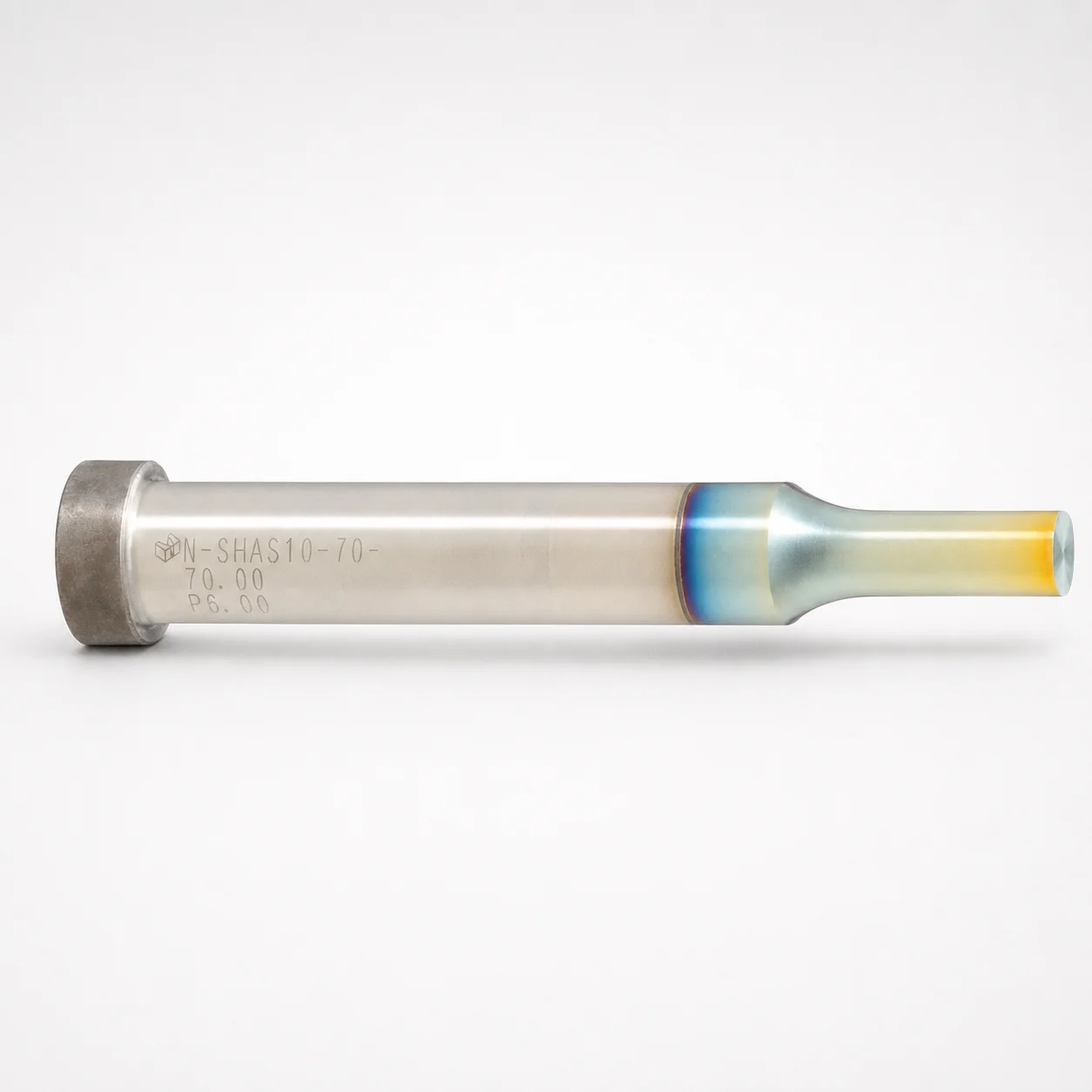
Single-Stepped Shoulder Punches - DLC Coating
Single-stepped shoulder punches (DLC coating) provide stable guidance for punch operations where repeatability and surface protection are critical. The DLC (XCD) finish helps reduce friction and wear during production.
- Single-stepped shank geometry for controlled positioning and consistent punch stroke
- DLC (XCD) coating improves wear resistance and lowers tool-to-work friction
- 5 mm head thickness (T) supports balanced load distribution in die sets
- Standard shank mounting compatibility for efficient installation in tooling assemblies
Specifications
20564 configurations available
| Tip shape | Material | Shank diameter D tolerance | B (Tip length) | D (Shank diameter) (mm) | L (L dimension) (mm) | LC (Full length alteration) (mm) | LCT (Head thickness tolerance change + total length alteration) (mm) | LMT(Head thickness tolerance change+Full length change) (mm) | Dimension P | PC (Tip dimension alteration) (mm) | Dimension R | Dimension W | WC (Tip dimension alteration) (mm) | type |
|---|---|---|---|---|---|---|---|---|---|---|---|---|---|---|
| Round | SKH40 Equivalent (Powdered High-Speed Steel) | +0.005/0 | L | 3 | 50 ~ 100 | - | - | - | 1 ~ 2.99 | - | - | - | - | - |
| Round | SKH40 Equivalent (Powdered High-Speed Steel) | +0.005/0 | L | 3 | - | 27 ~ 99.9 | - | - | 1 ~ 2.99 | - | - | - | - | - |
| Round | SKH40 Equivalent (Powdered High-Speed Steel) | +0.005/0 | L | 3 | - | - | 27 ~ 99.9 | - | 1 ~ 2.99 | - | - | - | - | - |
| Round | SKH40 Equivalent (Powdered High-Speed Steel) | +0.005/0 | L | 3 | - | - | - | 27 ~ 99.9 | 1 ~ 2.99 | - | - | - | - | - |
| Round | SKH40 Equivalent (Powdered High-Speed Steel) | +0.005/0 | L | 4 | 50 ~ 100 | - | - | - | 1 ~ 3.99 | - | - | - | - | - |
| Round | SKH40 Equivalent (Powdered High-Speed Steel) | +0.005/0 | L | 4 | - | 27 ~ 99.9 | - | - | 1 ~ 3.99 | - | - | - | - | - |
| Round | SKH40 Equivalent (Powdered High-Speed Steel) | +0.005/0 | L | 4 | - | - | 27 ~ 99.9 | - | 1 ~ 3.99 | - | - | - | - | - |
| Round | SKH40 Equivalent (Powdered High-Speed Steel) | +0.005/0 | L | 4 | - | - | - | 27 ~ 99.9 | 1 ~ 3.99 | - | - | - | - | - |
| Round | SKH40 Equivalent (Powdered High-Speed Steel) | +0.005/0 | L | 5 | 50 ~ 100 | - | - | - | 2 ~ 4.99 | - | - | - | - | - |
| Round | SKH40 Equivalent (Powdered High-Speed Steel) | +0.005/0 | L | 5 | 50 ~ 100 | - | - | - | - | 1 ~ 1.99 | - | - | - | - |
| Round | SKH40 Equivalent (Powdered High-Speed Steel) | +0.005/0 | L | 5 | - | 27 ~ 99.9 | - | - | 2 ~ 4.99 | - | - | - | - | - |
| Round | SKH40 Equivalent (Powdered High-Speed Steel) | +0.005/0 | L | 5 | - | 27 ~ 99.9 | - | - | - | 1 ~ 1.99 | - | - | - | - |
| Round | SKH40 Equivalent (Powdered High-Speed Steel) | +0.005/0 | L | 5 | - | - | 27 ~ 99.9 | - | 2 ~ 4.99 | - | - | - | - | - |
| Round | SKH40 Equivalent (Powdered High-Speed Steel) | +0.005/0 | L | 5 | - | - | 27 ~ 99.9 | - | - | 1 ~ 1.99 | - | - | - | - |
| Round | SKH40 Equivalent (Powdered High-Speed Steel) | +0.005/0 | L | 5 | - | - | - | 27 ~ 99.9 | 2 ~ 4.99 | - | - | - | - | - |
| Round | SKH40 Equivalent (Powdered High-Speed Steel) | +0.005/0 | L | 5 | - | - | - | 27 ~ 99.9 | - | 1 ~ 1.99 | - | - | - | - |
| Round | SKH40 Equivalent (Powdered High-Speed Steel) | +0.005/0 | L | 6 | 50 ~ 100 | - | - | - | 2 ~ 5.99 | - | - | - | - | - |
| Round | SKH40 Equivalent (Powdered High-Speed Steel) | +0.005/0 | L | 6 | 50 ~ 100 | - | - | - | - | 1 ~ 1.99 | - | - | - | - |
| Round | SKH40 Equivalent (Powdered High-Speed Steel) | +0.005/0 | L | 6 | - | 27 ~ 99.9 | - | - | 2 ~ 5.99 | - | - | - | - | - |
| Round | SKH40 Equivalent (Powdered High-Speed Steel) | +0.005/0 | L | 6 | - | 27 ~ 99.9 | - | - | - | 1 ~ 1.99 | - | - | - | - |
| Round | SKH40 Equivalent (Powdered High-Speed Steel) | +0.005/0 | L | 6 | - | - | 27 ~ 99.9 | - | 2 ~ 5.99 | - | - | - | - | - |
| Round | SKH40 Equivalent (Powdered High-Speed Steel) | +0.005/0 | L | 6 | - | - | 27 ~ 99.9 | - | - | 1 ~ 1.99 | - | - | - | - |
| Round | SKH40 Equivalent (Powdered High-Speed Steel) | +0.005/0 | L | 6 | - | - | - | 27 ~ 99.9 | 2 ~ 5.99 | - | - | - | - | - |
| Round | SKH40 Equivalent (Powdered High-Speed Steel) | +0.005/0 | L | 6 | - | - | - | 27 ~ 99.9 | - | 1 ~ 1.99 | - | - | - | - |
| Round | SKH40 Equivalent (Powdered High-Speed Steel) | +0.005/0 | L | 8 | 50 ~ 100 | - | - | - | 3 ~ 7.99 | - | - | - | - | - |
| Round | SKH40 Equivalent (Powdered High-Speed Steel) | +0.005/0 | L | 8 | 50 ~ 100 | - | - | - | - | 1.5 ~ 2.99 | - | - | - | - |
| Round | SKH40 Equivalent (Powdered High-Speed Steel) | +0.005/0 | L | 8 | - | 27 ~ 99.9 | - | - | 3 ~ 7.99 | - | - | - | - | - |
| Round | SKH40 Equivalent (Powdered High-Speed Steel) | +0.005/0 | L | 8 | - | 27 ~ 99.9 | - | - | - | 1.5 ~ 2.99 | - | - | - | - |
| Round | SKH40 Equivalent (Powdered High-Speed Steel) | +0.005/0 | L | 8 | - | - | 27 ~ 99.9 | - | 3 ~ 7.99 | - | - | - | - | - |
| Round | SKH40 Equivalent (Powdered High-Speed Steel) | +0.005/0 | L | 8 | - | - | 27 ~ 99.9 | - | - | 1.5 ~ 2.99 | - | - | - | - |
| Round | SKH40 Equivalent (Powdered High-Speed Steel) | +0.005/0 | L | 8 | - | - | - | 27 ~ 99.9 | 3 ~ 7.99 | - | - | - | - | - |
| Round | SKH40 Equivalent (Powdered High-Speed Steel) | +0.005/0 | L | 8 | - | - | - | 27 ~ 99.9 | - | 1.5 ~ 2.99 | - | - | - | - |
| Round | SKH40 Equivalent (Powdered High-Speed Steel) | +0.005/0 | L | 10 | 50 ~ 100 | - | - | - | 3 ~ 9.99 | - | - | - | - | - |
| Round | SKH40 Equivalent (Powdered High-Speed Steel) | +0.005/0 | L | 10 | 50 ~ 100 | - | - | - | - | 1.5 ~ 2.99 | - | - | - | - |
| Round | SKH40 Equivalent (Powdered High-Speed Steel) | +0.005/0 | L | 10 | - | 27 ~ 99.9 | - | - | 3 ~ 9.99 | - | - | - | - | - |
| Round | SKH40 Equivalent (Powdered High-Speed Steel) | +0.005/0 | L | 10 | - | 27 ~ 99.9 | - | - | - | 1.5 ~ 2.99 | - | - | - | - |
| Round | SKH40 Equivalent (Powdered High-Speed Steel) | +0.005/0 | L | 10 | - | - | 27 ~ 99.9 | - | 3 ~ 9.99 | - | - | - | - | - |
| Round | SKH40 Equivalent (Powdered High-Speed Steel) | +0.005/0 | L | 10 | - | - | 27 ~ 99.9 | - | - | 1.5 ~ 2.99 | - | - | - | - |
| Round | SKH40 Equivalent (Powdered High-Speed Steel) | +0.005/0 | L | 10 | - | - | - | 27 ~ 99.9 | 3 ~ 9.99 | - | - | - | - | - |
| Round | SKH40 Equivalent (Powdered High-Speed Steel) | +0.005/0 | L | 10 | - | - | - | 27 ~ 99.9 | - | 1.5 ~ 2.99 | - | - | - | - |
| Round | SKH40 Equivalent (Powdered High-Speed Steel) | +0.005/0 | L | 13 | 50 ~ 100 | - | - | - | 6 ~ 12.99 | - | - | - | - | - |
| Round | SKH40 Equivalent (Powdered High-Speed Steel) | +0.005/0 | L | 13 | 50 ~ 100 | - | - | - | - | 3 ~ 5.99 | - | - | - | - |
| Round | SKH40 Equivalent (Powdered High-Speed Steel) | +0.005/0 | L | 13 | - | 27 ~ 99.9 | - | - | 6 ~ 12.99 | - | - | - | - | - |
| Round | SKH40 Equivalent (Powdered High-Speed Steel) | +0.005/0 | L | 13 | - | 27 ~ 99.9 | - | - | - | 3 ~ 5.99 | - | - | - | - |
| Round | SKH40 Equivalent (Powdered High-Speed Steel) | +0.005/0 | L | 13 | - | - | 27 ~ 99.9 | - | 6 ~ 12.99 | - | - | - | - | - |
| Round | SKH40 Equivalent (Powdered High-Speed Steel) | +0.005/0 | L | 13 | - | - | 27 ~ 99.9 | - | - | 3 ~ 5.99 | - | - | - | - |
| Round | SKH40 Equivalent (Powdered High-Speed Steel) | +0.005/0 | L | 13 | - | - | - | 27 ~ 99.9 | 6 ~ 12.99 | - | - | - | - | - |
| Round | SKH40 Equivalent (Powdered High-Speed Steel) | +0.005/0 | L | 13 | - | - | - | 27 ~ 99.9 | - | 3 ~ 5.99 | - | - | - | - |
| Round | SKH40 Equivalent (Powdered High-Speed Steel) | +0.005/0 | L | 16 | 60 ~ 100 | - | - | - | 10 ~ 15.99 | - | - | - | - | - |
| Round | SKH40 Equivalent (Powdered High-Speed Steel) | +0.005/0 | L | 16 | 60 ~ 100 | - | - | - | - | 5 ~ 9.99 | - | - | - | - |
Product Guide
Application Scenarios+
This type of single-stepped shoulder punch is used inside close-tolerance die sets where the punch must remain precisely guided throughout repetitive strokes. The DLC (XCD) surface finish is especially suited to applications that demand clean, controlled action with minimized metal-to-metal friction and wear.
- Automotive connector and sensor housings: In multi-cavity progressive tooling, the stepped shoulder helps maintain consistent positioning between tool sets, while the DLC coating supports long production runs by reducing wear on the working surfaces.
- Electrical terminal and contact forming: When punching and piercing operations require stable stroke-to-stroke repeatability, the shoulder geometry provides reliable alignment; the low-friction coating helps prevent galling during high-cycle output.
- Precision brackets and enclosures: For part features with tight dimensional control, the guided shank behavior supports repeatable piercing, and the DLC finish improves tool surface longevity under sliding contact.
Material & Process Details+
These punches are offered in two high-speed steel (HSS) options with different performance balances: SKH40 Equivalent (powdered HSS) and SKH51 Equivalent (M2). SKH51 (M2) is typically selected for higher wear resistance and hot hardness characteristics, while SKH40 (powdered) can offer improved uniformity and edge stability for demanding cycles.
The DLC (XCD) coating adds a hard, low-friction layer that reduces tool-to-work friction and helps limit abrasive/adhesive wear at the contact surfaces. Heat treatment is specific to the supplied HSS grade and punch design; the intent is a hardened, wear-capable HSS base followed by DLC deposition to further protect the working geometry.
- Hardness/behavior: Choose HSS based on wear vs. toughness needs—higher wear resistance can slightly reduce toughness margin depending on the chosen HSS grade and resulting hardness.
- Trade-off: DLC improves surface wear behavior, but ultimate resistance still depends on the hardened HSS substrate and the load/impact conditions of the punch operation.
Sizing & Selection Guide+
Selection starts by matching the punch shank diameter D and overall length to the die holder and guide requirements. Available shank diameters are 3 to 25 mm, and the D tolerance is +0.005/0, m5, so the punch fit should be specified against the corresponding guide/bore tolerance to avoid binding while maintaining positional stability.
- Choose head/tip dimensions: Tip shapes include round, rectangle, oblong, double flatted round, radius rectangle. Tip length variants use B values labeled L, S, X, and tip dimension alteration ranges include P = 1 to 18 and PC = 1 to 9, with tip dimension ranges such as W = 1 to 6 and WC = 1 to 3.
- Match length and shoulder geometry: L (L dimension) is offered in groups such as 50–100, 60–100, 40–100, and 70–100 mm. Full length alteration LC and head-thickness/total-length change ranges are provided as 27 to 90.1 mm, which directly affect how the shoulder seats within the die set.
- Guidance: Use the selected LC and thickness-change parameters (LCT/LMT ranges) to ensure the head thickness and total length align with cavity/core stroke depth and clearance.
Frequently Asked Questions
Which HSS base grade should I choose for repeated piercing wear: SKH40 (powdered) or SKH51 (M2 equivalent)?+
Both options are available for the same punch configuration, with SKH51 Equivalent (M2) generally used when you prioritize wear resistance and hot hardness behavior. SKH40 Equivalent (powdered HSS) can be selected when you want strong edge stability and consistent performance from a powdered microstructure.
The final wear outcome also depends on the DLC (XCD) coating and your load/part-material characteristics.
How does the DLC (XCD) coating improve punch performance in close-tolerance die sets?+
The DLC (XCD) finish is designed to reduce tool-to-work friction and improve surface protection during repeated strokes. In close-tolerance tooling, this helps maintain stable punch action by limiting friction-driven wear and reducing the risk of galling under sliding contact.
Its effectiveness complements, but does not replace, correct base HSS hardness and proper fit to the guide components.
What dimensional parameters control the stepped shoulder seating when selecting LC, LCT, and LMT?+
The punch provides configurable alterations via LC (full length alteration) and head-thickness-related changes through LCT and LMT, each specified within 27 to 90.1 mm ranges. These parameters affect how the head and overall length relate to the die set stack-up.
Confirm stroke depth, clearance, and seating position by matching the selected alteration values to the required cavity/core engagement.
What shank fit tolerance is available for D, and how should I account for it in my guide/bushing design?+
The shank diameter D range is 3 to 25 mm, with a specified tolerance of +0.005/0, m5. This means your guide/bore should be designed to provide clearance for smooth movement while maintaining enough guidance to preserve repeatability.
When integrating into a die set, align the guide tolerance with the punch’s D tolerance to prevent binding or excessive play.
How do I select the correct overall length L for my die set if I’m targeting a specific clearance?+
L (L dimension) is offered in multiple ranges including 50–100, 60–100, 40–100, and 70–100 mm. Choose the closest base L that matches your stack-up, then use LC and the head-thickness/total-length change ranges (LCT or LMT) to fine-tune the final seating and engagement.
Verify that the total length and shoulder position achieve your required clearance for the punch stroke.
Related Products






Need Custom Specifications?
Our engineering team can help with custom configurations, material selection, and volume pricing.