
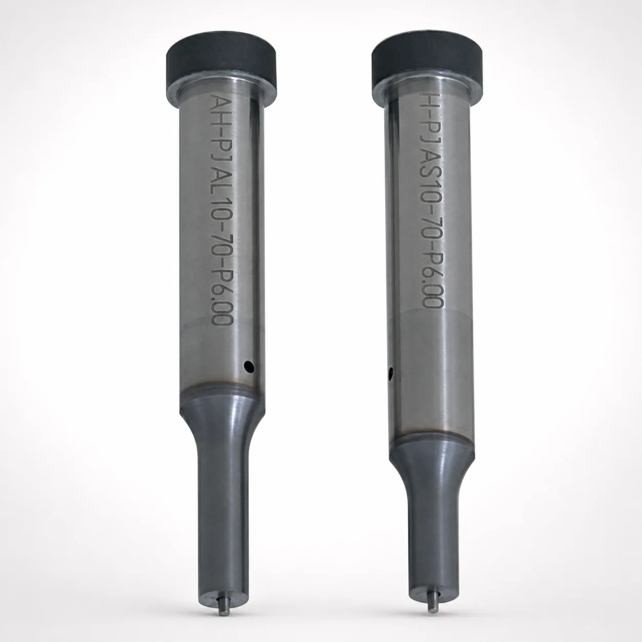
Shoulder Punches Double-Stepped Shank
Shoulder Punches with a double-stepped shank deliver heavy-load punching performance with dependable dimensional stability. Built without a jector and available in multiple tip geometries, they help maintain consistent punch alignment across production runs.
- Double-stepped shank design for stable seating under heavy punch load
- Hardened steel options for strong wear resistance in repeated cycles
- Tip geometry choices (Round, Rectangle, Radius Rectangle, Oblong, Double-Flatted Round) for die matching
- Designed for precision tooling applications where long service life matters
Specifications
9025 configurations available
| Tip shape | Material | Shank diameter D tolerance | B (Tip length) | D (Shank diameter) (mm) | P (Tip dimension) (mm) | L (L dimension) (mm) | LC (Full length alteration) (mm) | LCT (Head thickness tolerance change + Total length alteration) (mm) | LMT (Head thickness tolerance change + Total length alteration) (mm) | PC (Tip dimension alteration) (mm) | R (Tip corner R) (mm) | W (Tip dimension) (mm) | WC (Tip dimension alteration) (mm) | type |
|---|---|---|---|---|---|---|---|---|---|---|---|---|---|---|
| Round | SKH40 Equivalent (Powdered High-Speed Steel) | +0.005/0 | L | 3 | 1 ~ 2.99 | 50 ~ 100 | - | - | - | - | - | - | - | - |
| Round | SKH40 Equivalent (Powdered High-Speed Steel) | +0.005/0 | L | 3 | - | 50 ~ 100 | - | - | - | 0.5 ~ 0.99 | - | - | - | - |
| Round | SKH40 Equivalent (Powdered High-Speed Steel) | +0.005/0 | L | 3 | 1 ~ 2.99 | - | 27 ~ 99.9 | - | - | - | - | - | - | - |
| Round | SKH40 Equivalent (Powdered High-Speed Steel) | +0.005/0 | L | 3 | - | - | 27 ~ 99.9 | - | - | 0.5 ~ 0.99 | - | - | - | - |
| Round | SKH40 Equivalent (Powdered High-Speed Steel) | +0.005/0 | L | 3 | 1 ~ 2.99 | - | - | 27 ~ 99.9 | - | - | - | - | - | - |
| Round | SKH40 Equivalent (Powdered High-Speed Steel) | +0.005/0 | L | 3 | - | - | - | 27 ~ 99.9 | - | 0.5 ~ 0.99 | - | - | - | - |
| Round | SKH40 Equivalent (Powdered High-Speed Steel) | +0.005/0 | L | 3 | 1 ~ 2.99 | - | - | - | 27 ~ 99.9 | - | - | - | - | - |
| Round | SKH40 Equivalent (Powdered High-Speed Steel) | +0.005/0 | L | 3 | - | - | - | - | 27 ~ 99.9 | 0.5 ~ 0.99 | - | - | - | - |
| Round | SKH40 Equivalent (Powdered High-Speed Steel) | +0.005/0 | L | 4 | 1 ~ 3.99 | 50 ~ 100 | - | - | - | - | - | - | - | - |
| Round | SKH40 Equivalent (Powdered High-Speed Steel) | +0.005/0 | L | 4 | - | 50 ~ 100 | - | - | - | 0.5 ~ 0.99 | - | - | - | - |
| Round | SKH40 Equivalent (Powdered High-Speed Steel) | +0.005/0 | L | 4 | 1 ~ 3.99 | - | 27 ~ 99.9 | - | - | - | - | - | - | - |
| Round | SKH40 Equivalent (Powdered High-Speed Steel) | +0.005/0 | L | 4 | - | - | 27 ~ 99.9 | - | - | 0.5 ~ 0.99 | - | - | - | - |
| Round | SKH40 Equivalent (Powdered High-Speed Steel) | +0.005/0 | L | 4 | 1 ~ 3.99 | - | - | 27 ~ 99.9 | - | - | - | - | - | - |
| Round | SKH40 Equivalent (Powdered High-Speed Steel) | +0.005/0 | L | 4 | - | - | - | 27 ~ 99.9 | - | 0.5 ~ 0.99 | - | - | - | - |
| Round | SKH40 Equivalent (Powdered High-Speed Steel) | +0.005/0 | L | 4 | 1 ~ 3.99 | - | - | - | 27 ~ 99.9 | - | - | - | - | - |
| Round | SKH40 Equivalent (Powdered High-Speed Steel) | +0.005/0 | L | 4 | - | - | - | - | 27 ~ 99.9 | 0.5 ~ 0.99 | - | - | - | - |
| Round | SKH40 Equivalent (Powdered High-Speed Steel) | +0.005/0 | L | 5 | 2 ~ 4.99 | 50 ~ 100 | - | - | - | - | - | - | - | - |
| Round | SKH40 Equivalent (Powdered High-Speed Steel) | +0.005/0 | L | 5 | - | 50 ~ 100 | - | - | - | 1 ~ 1.99 | - | - | - | - |
| Round | SKH40 Equivalent (Powdered High-Speed Steel) | +0.005/0 | L | 5 | 2 ~ 4.99 | - | 27 ~ 99.9 | - | - | - | - | - | - | - |
| Round | SKH40 Equivalent (Powdered High-Speed Steel) | +0.005/0 | L | 5 | - | - | 27 ~ 99.9 | - | - | 1 ~ 1.99 | - | - | - | - |
| Round | SKH40 Equivalent (Powdered High-Speed Steel) | +0.005/0 | L | 5 | 2 ~ 4.99 | - | - | 27 ~ 99.9 | - | - | - | - | - | - |
| Round | SKH40 Equivalent (Powdered High-Speed Steel) | +0.005/0 | L | 5 | - | - | - | 27 ~ 99.9 | - | 1 ~ 1.99 | - | - | - | - |
| Round | SKH40 Equivalent (Powdered High-Speed Steel) | +0.005/0 | L | 5 | 2 ~ 4.99 | - | - | - | 27 ~ 99.9 | - | - | - | - | - |
| Round | SKH40 Equivalent (Powdered High-Speed Steel) | +0.005/0 | L | 5 | - | - | - | - | 27 ~ 99.9 | 1 ~ 1.99 | - | - | - | - |
| Round | SKH40 Equivalent (Powdered High-Speed Steel) | +0.005/0 | L | 6 | 2 ~ 5.99 | 50 ~ 100 | - | - | - | - | - | - | - | - |
| Round | SKH40 Equivalent (Powdered High-Speed Steel) | +0.005/0 | L | 6 | - | 50 ~ 100 | - | - | - | 1 ~ 1.99 | - | - | - | - |
| Round | SKH40 Equivalent (Powdered High-Speed Steel) | +0.005/0 | L | 6 | 2 ~ 5.99 | - | 27 ~ 99.9 | - | - | - | - | - | - | - |
| Round | SKH40 Equivalent (Powdered High-Speed Steel) | +0.005/0 | L | 6 | - | - | 27 ~ 99.9 | - | - | 1 ~ 1.99 | - | - | - | - |
| Round | SKH40 Equivalent (Powdered High-Speed Steel) | +0.005/0 | L | 6 | 2 ~ 5.99 | - | - | 27 ~ 99.9 | - | - | - | - | - | - |
| Round | SKH40 Equivalent (Powdered High-Speed Steel) | +0.005/0 | L | 6 | - | - | - | 27 ~ 99.9 | - | 1 ~ 1.99 | - | - | - | - |
| Round | SKH40 Equivalent (Powdered High-Speed Steel) | +0.005/0 | L | 6 | 2 ~ 5.99 | - | - | - | 27 ~ 99.9 | - | - | - | - | - |
| Round | SKH40 Equivalent (Powdered High-Speed Steel) | +0.005/0 | L | 6 | - | - | - | - | 27 ~ 99.9 | 1 ~ 1.99 | - | - | - | - |
| Round | SKH40 Equivalent (Powdered High-Speed Steel) | +0.005/0 | L | 8 | 3 ~ 7.99 | 50 ~ 100 | - | - | - | - | - | - | - | - |
| Round | SKH40 Equivalent (Powdered High-Speed Steel) | +0.005/0 | L | 8 | - | 50 ~ 100 | - | - | - | 1.5 ~ 2.99 | - | - | - | - |
| Round | SKH40 Equivalent (Powdered High-Speed Steel) | +0.005/0 | L | 8 | 3 ~ 7.99 | - | 27 ~ 99.9 | - | - | - | - | - | - | - |
| Round | SKH40 Equivalent (Powdered High-Speed Steel) | +0.005/0 | L | 8 | - | - | 27 ~ 99.9 | - | - | 1.5 ~ 2.99 | - | - | - | - |
| Round | SKH40 Equivalent (Powdered High-Speed Steel) | +0.005/0 | L | 8 | 3 ~ 7.99 | - | - | 27 ~ 99.9 | - | - | - | - | - | - |
| Round | SKH40 Equivalent (Powdered High-Speed Steel) | +0.005/0 | L | 8 | - | - | - | 27 ~ 99.9 | - | 1.5 ~ 2.99 | - | - | - | - |
| Round | SKH40 Equivalent (Powdered High-Speed Steel) | +0.005/0 | L | 8 | 3 ~ 7.99 | - | - | - | 27 ~ 99.9 | - | - | - | - | - |
| Round | SKH40 Equivalent (Powdered High-Speed Steel) | +0.005/0 | L | 8 | - | - | - | - | 27 ~ 99.9 | 1.5 ~ 2.99 | - | - | - | - |
| Round | SKH40 Equivalent (Powdered High-Speed Steel) | +0.005/0 | L | 10 | 3 ~ 9.99 | 50 ~ 100 | - | - | - | - | - | - | - | - |
| Round | SKH40 Equivalent (Powdered High-Speed Steel) | +0.005/0 | L | 10 | - | 50 ~ 100 | - | - | - | 1.5 ~ 2.99 | - | - | - | - |
| Round | SKH40 Equivalent (Powdered High-Speed Steel) | +0.005/0 | L | 10 | 3 ~ 9.99 | - | 27 ~ 99.9 | - | - | - | - | - | - | - |
| Round | SKH40 Equivalent (Powdered High-Speed Steel) | +0.005/0 | L | 10 | - | - | 27 ~ 99.9 | - | - | 1.5 ~ 2.99 | - | - | - | - |
| Round | SKH40 Equivalent (Powdered High-Speed Steel) | +0.005/0 | L | 10 | 3 ~ 9.99 | - | - | 27 ~ 99.9 | - | - | - | - | - | - |
| Round | SKH40 Equivalent (Powdered High-Speed Steel) | +0.005/0 | L | 10 | - | - | - | 27 ~ 99.9 | - | 1.5 ~ 2.99 | - | - | - | - |
| Round | SKH40 Equivalent (Powdered High-Speed Steel) | +0.005/0 | L | 10 | 3 ~ 9.99 | - | - | - | 27 ~ 99.9 | - | - | - | - | - |
| Round | SKH40 Equivalent (Powdered High-Speed Steel) | +0.005/0 | L | 10 | - | - | - | - | 27 ~ 99.9 | 1.5 ~ 2.99 | - | - | - | - |
| Round | SKH40 Equivalent (Powdered High-Speed Steel) | +0.005/0 | L | 13 | 6 ~ 12.99 | 50 ~ 100 | - | - | - | - | - | - | - | - |
| Round | SKH40 Equivalent (Powdered High-Speed Steel) | +0.005/0 | L | 13 | - | 50 ~ 100 | - | - | - | 3 ~ 5.99 | - | - | - | - |
Product Guide
Application Scenarios+
Double-stepped shank shoulder punches are used in injection mold tooling where a punch must hold position reliably under repeated, high contact loads. The double-step shank design improves seating stability in the holder, helping maintain consistent punch alignment through production cycles.
- Automotive connector and terminal molds: ideal for piercing/blanking operations where the punch is exposed to frequent cycles and must resist wear while maintaining head height and seating integrity.
- Electronics and housings (high-volume precision tooling): suited for applications that require dependable dimensional stability in the punch length region (L and LC), reducing variation at the die interface.
- Medical device component molds (tight assembly fit): hardened steel options support long service life and stable punch seating, which helps prevent drift in the shoulder region that can affect part features.
Tip geometry choices (Round, Rectangle, Oblong, Radius Rectangle, Double-Flatted Round) allow matching to die openings for controlled edge formation and predictable wear patterns.
Material & Process Details+
These shoulder punches are offered in SKH40-equivalent (powdered high-speed steel), SKH51-equivalent (M2), and SKD11-equivalent (D2) variants. SKH51 (M2) is typically selected for a balance of wear resistance and toughness for high-cycle punching. SKD11 (D2) emphasizes hardness and edge durability, but can be more sensitive to impact than HSS grades depending on conditions.
- SKH40-equivalent: powdered HSS for good wear resistance in repeated cycles.
- SKH51-equivalent (M2): high-speed steel for improved wear resistance while retaining workable toughness.
- SKD11-equivalent (D2): tool steel grade for strong edge retention in abrasive or long-run use.
All variants are supplied in a hardened steel configuration per the product’s hardened options intent, supporting stable punch seating and longer service life. Exact HRC values and heat-treatment recipes are not specified in the provided data, so final hardness selection should be confirmed against your tool’s load and required wear life.
Sizing & Selection Guide+
Selection starts with matching the shank diameter D, which is specified as 3 ~ 25 mm with a D tolerance of +0.005/0 (m5 fit). Choose the D that matches the holder/bushing bore so the punch seats firmly without excessive clearance that could cause shoulder-region variation.
- Tip geometry: select the required tip shape (Round, Rectangle, Oblong, Radius Rectangle, Double-Flatted Round) to match the die feature (P and the corner radius R).
- Tip dimensions: use P = 1 ~ 18 mm, W = 1 ~ 6 mm, and corner radius R = 0.15 mm (as listed) to align the cutting contact area. Account for tip dimension alteration PC = 0.5 ~ 9 mm where applicable.
- Length control: verify L = 40 ~ 100 mm and the full-length alteration LC = 26 ~ 80.09 mm, with head thickness tolerance change/total length alteration listed in 26 ~ 40 mm ranges.
After confirming D and tip geometry, ensure the chosen head thickness/total length alteration (LCT/LMT) is compatible with your die stack height and the required punch-to-cavity position. Fixed dimensions are governed by the spec ranges above; tolerances influence fit and long-term alignment.
Frequently Asked Questions
Which material variant should I choose between SKH40-equivalent, SKH51-equivalent (M2), and SKD11-equivalent (D2) for punch wear resistance?+
For long-run wear resistance, you can select among the provided hardened steel options: SKH51-equivalent (M2), SKD11-equivalent (D2), or SKH40-equivalent (powdered HSS). SKH51 (M2) is generally chosen when you want strong wear resistance with more balanced toughness than D2-style steels. If your application prioritizes edge durability under abrasive/high-cycle contact, D2-type (SKD11) is commonly considered within the product’s hardened options. Confirm the exact hardness (HRC) for your load case since specific HRC values are not included in the provided data.
How do I select the correct shank diameter D and fit tolerance for stable seating in the holder?+
The shank diameter D is specified as 3 ~ 25 mm with tolerance +0.005/0 and an m5 fit reference. Use the D that matches the holder/bushing bore to prevent excessive clearance at the double-step seating face. Stable seating under heavy punch load is the key function supported by this double-stepped shank geometry.
What tip dimension parameters (P, W, R) determine the cut/feature size on the punched part?+
The primary tip dimension parameter P is given as 1 ~ 18 mm, while W ranges 1 ~ 6 mm. The tip corner radius is listed as R = 0.15 mm, which is relevant for controlling stress concentration and edge geometry. The product also lists tip dimension alteration PC = 0.5 ~ 9 mm and corner/width-related alteration parameters, so verify those against the die opening requirements for your cavity/core.
How should I match the punch length (L, LC, and LCT/LMT) to my die stack-up and required total travel?+
Use L (40 ~ 100 mm) as the base length and then check the product’s listed full-length alteration LC (26 ~ 80.09 mm). The tolerances associated with head thickness/total length alteration are provided as LCT = 26 ~ 40 mm and LMT = 26 ~ 40 mm ranges. Ensure these values align with your press height, die stack-up, and the required punch-to-cavity position; otherwise shoulder alignment and feature depth can shift.
Which tip shapes are available, and how do they relate to die matching for shoulder punches?+
The available tip shapes are Round, Rectangle, Oblong, Double Flatted Round, and Radius Rectangle. Choose the shape that matches your die opening strategy so the cutting interface corresponds to your required feature profile. After selecting shape, confirm the related dimensional parameters P, W, and R for the exact edge contour and corner radius behavior.
Related Products





Need Custom Specifications?
Our engineering team can help with custom configurations, material selection, and volume pricing.