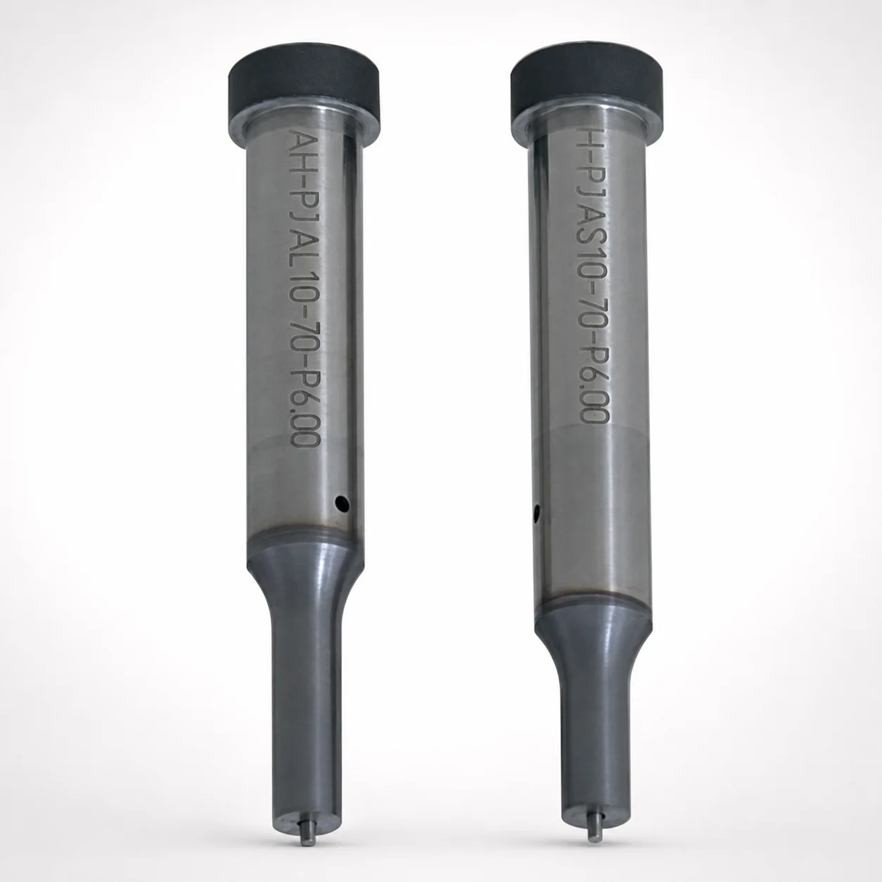
TiCN Coated Jector Punches
Jector Punches (TiCN coated) are engineered for reliable ejection in precision molding. A single-stepped shank and spring reinforced jector pin improve durability under demanding cycles while helping reduce wear.
- Heavy-load punch option supports stable operation in high-demand processes
- Spring reinforced jector pin design enhances impact resistance and longevity
- TiCN coating improves abrasion wear resistance for longer tool life
- Built for precision punch applications where consistent ejection accuracy matters
Specifications
14547 configurations available
| Jector | Tip shape | Shank diameter D tolerance | B (Tip length) | D (Shank diameter) (mm) | P (Tip dimension) (mm) | L (L dimension) (mm) | LC (Full length alteration) (mm) | LCT (Head thickness tolerance change + Total length alteration) (mm) | LMT (Head thickness tolerance change + Total length alteration) (mm) | PC (Tip dimension alteration) (mm) | R (Tip corner R) (mm) | W (Tip dimension) (mm) | WC (Tip dimension alteration) (mm) | type |
|---|---|---|---|---|---|---|---|---|---|---|---|---|---|---|
| Standard | Round | +0.005/0 | L | 4 | 1 ~ 3.99 | 50 ~ 80 | - | - | - | - | - | - | - | - |
| Standard | Round | +0.005/0 | L | 4 | 1 ~ 3.99 | - | 39 ~ 79.9 | - | - | - | - | - | - | - |
| Standard | Round | +0.005/0 | L | 4 | 1 ~ 3.99 | - | - | 39 ~ 79.9 | - | - | - | - | - | - |
| Standard | Round | +0.005/0 | L | 4 | 1 ~ 3.99 | - | - | - | 39 ~ 79.9 | - | - | - | - | - |
| Standard | Round | +0.005/0 | L | 5 | 2 ~ 4.99 | 50 ~ 80 | - | - | - | - | - | - | - | - |
| Standard | Round | +0.005/0 | L | 5 | - | 50 ~ 80 | - | - | - | 1.8 ~ 1.99 | - | - | - | - |
| Standard | Round | +0.005/0 | L | 5 | 2 ~ 4.99 | - | 39 ~ 79.9 | - | - | - | - | - | - | - |
| Standard | Round | +0.005/0 | L | 5 | - | - | 39 ~ 79.9 | - | - | 1.8 ~ 1.99 | - | - | - | - |
| Standard | Round | +0.005/0 | L | 5 | 2 ~ 4.99 | - | - | 39 ~ 79.9 | - | - | - | - | - | - |
| Standard | Round | +0.005/0 | L | 5 | - | - | - | 39 ~ 79.9 | - | 1.8 ~ 1.99 | - | - | - | - |
| Standard | Round | +0.005/0 | L | 5 | 2 ~ 4.99 | - | - | - | 39 ~ 79.9 | - | - | - | - | - |
| Standard | Round | +0.005/0 | L | 5 | - | - | - | - | 39 ~ 79.9 | 1.8 ~ 1.99 | - | - | - | - |
| Standard | Round | +0.005/0 | L | 6 | 2 ~ 5.99 | 50 ~ 80 | - | - | - | - | - | - | - | - |
| Standard | Round | +0.005/0 | L | 6 | - | 50 ~ 80 | - | - | - | 1.8 ~ 1.99 | - | - | - | - |
| Standard | Round | +0.005/0 | L | 6 | 2 ~ 5.99 | - | 39 ~ 79.9 | - | - | - | - | - | - | - |
| Standard | Round | +0.005/0 | L | 6 | - | - | 39 ~ 79.9 | - | - | 1.8 ~ 1.99 | - | - | - | - |
| Standard | Round | +0.005/0 | L | 6 | 2 ~ 5.99 | - | - | 39 ~ 79.9 | - | - | - | - | - | - |
| Standard | Round | +0.005/0 | L | 6 | - | - | - | 39 ~ 79.9 | - | 1.8 ~ 1.99 | - | - | - | - |
| Standard | Round | +0.005/0 | L | 6 | 2 ~ 5.99 | - | - | - | 39 ~ 79.9 | - | - | - | - | - |
| Standard | Round | +0.005/0 | L | 6 | - | - | - | - | 39 ~ 79.9 | 1.8 ~ 1.99 | - | - | - | - |
| Standard | Round | +0.005/0 | L | 8 | 3 ~ 7.99 | 50 ~ 100 | - | - | - | - | - | - | - | - |
| Standard | Round | +0.005/0 | L | 8 | - | 50 ~ 100 | - | - | - | 2.5 ~ 2.99 | - | - | - | - |
| Standard | Round | +0.005/0 | L | 8 | 3 ~ 7.99 | - | 33 ~ 99.9 | - | - | - | - | - | - | - |
| Standard | Round | +0.005/0 | L | 8 | - | - | 33 ~ 99.9 | - | - | 2.5 ~ 2.99 | - | - | - | - |
| Standard | Round | +0.005/0 | L | 8 | 3 ~ 7.99 | - | - | 33 ~ 99.9 | - | - | - | - | - | - |
| Standard | Round | +0.005/0 | L | 8 | - | - | - | 33 ~ 99.9 | - | 2.5 ~ 2.99 | - | - | - | - |
| Standard | Round | +0.005/0 | L | 8 | 3 ~ 7.99 | - | - | - | 33 ~ 99.9 | - | - | - | - | - |
| Standard | Round | +0.005/0 | L | 8 | - | - | - | - | 33 ~ 99.9 | 2.5 ~ 2.99 | - | - | - | - |
| Standard | Round | +0.005/0 | L | 10 | 3 ~ 9.99 | 50 ~ 100 | - | - | - | - | - | - | - | - |
| Standard | Round | +0.005/0 | L | 10 | - | 50 ~ 100 | - | - | - | 2.8 ~ 2.99 | - | - | - | - |
| Standard | Round | +0.005/0 | L | 10 | 3 ~ 9.99 | - | 33 ~ 99.9 | - | - | - | - | - | - | - |
| Standard | Round | +0.005/0 | L | 10 | - | - | 33 ~ 99.9 | - | - | 2.8 ~ 2.99 | - | - | - | - |
| Standard | Round | +0.005/0 | L | 10 | 3 ~ 9.99 | - | - | 33 ~ 99.9 | - | - | - | - | - | - |
| Standard | Round | +0.005/0 | L | 10 | - | - | - | 33 ~ 99.9 | - | 2.8 ~ 2.99 | - | - | - | - |
| Standard | Round | +0.005/0 | L | 10 | 3 ~ 9.99 | - | - | - | 33 ~ 99.9 | - | - | - | - | - |
| Standard | Round | +0.005/0 | L | 10 | - | - | - | - | 33 ~ 99.9 | 2.8 ~ 2.99 | - | - | - | - |
| Standard | Round | +0.005/0 | L | 13 | 6 ~ 12.99 | 50 ~ 100 | - | - | - | - | - | - | - | - |
| Standard | Round | +0.005/0 | L | 13 | - | 50 ~ 100 | - | - | - | 5 ~ 5.99 | - | - | - | - |
| Standard | Round | +0.005/0 | L | 13 | 6 ~ 12.99 | - | 33 ~ 99.9 | - | - | - | - | - | - | - |
| Standard | Round | +0.005/0 | L | 13 | - | - | 33 ~ 99.9 | - | - | 5 ~ 5.99 | - | - | - | - |
| Standard | Round | +0.005/0 | L | 13 | 6 ~ 12.99 | - | - | 33 ~ 99.9 | - | - | - | - | - | - |
| Standard | Round | +0.005/0 | L | 13 | - | - | - | 33 ~ 99.9 | - | 5 ~ 5.99 | - | - | - | - |
| Standard | Round | +0.005/0 | L | 13 | 6 ~ 12.99 | - | - | - | 33 ~ 99.9 | - | - | - | - | - |
| Standard | Round | +0.005/0 | L | 13 | - | - | - | - | 33 ~ 99.9 | 5 ~ 5.99 | - | - | - | - |
| Standard | Round | +0.005/0 | L | 16 | 10 ~ 15.99 | 60 ~ 100 | - | - | - | - | - | - | - | - |
| Standard | Round | +0.005/0 | L | 16 | - | 60 ~ 100 | - | - | - | 8 ~ 9.99 | - | - | - | - |
| Standard | Round | +0.005/0 | L | 16 | 10 ~ 15.99 | - | 37 ~ 99.9 | - | - | - | - | - | - | - |
| Standard | Round | +0.005/0 | L | 16 | - | - | 37 ~ 99.9 | - | - | 8 ~ 9.99 | - | - | - | - |
| Standard | Round | +0.005/0 | L | 16 | 10 ~ 15.99 | - | - | 37 ~ 99.9 | - | - | - | - | - | - |
| Standard | Round | +0.005/0 | L | 16 | - | - | - | 37 ~ 99.9 | - | 8 ~ 9.99 | - | - | - | - |
Product Guide
Application Scenarios+
This jector punch is used in injection mold tooling wherever repeatable part ejection demands high cycle stability and reduced wear at the pin tip. The TiCN surface is particularly suited to environments with abrasive contact against cores/cavities, helping maintain ejection consistency over long runs.
- Automotive connector and sensor housings: Ideal for ejection in high-cycle molds with tight functional surfaces, where the round or rectangle tip shapes and the spring reinforced option can better absorb impact during ejector travel.
- Consumer electronics housings: Suits precision ejector systems that require controlled tip geometry (e.g., oblong, double flatted round, radius rectangle) to match gate/part contours while limiting abrasion-driven dimensional drift.
- Appliance and industrial component molds: The heavy-load variant supports stable operation under higher ejection force profiles, while the spring reinforced jector configuration improves impact resistance for reliable ejection.
Material & Process Details+
As a TiCN coated jector punch set, the functional performance relies on the hard TiCN coating for abrasion resistance at the contacting tip. While the base steel grade is not specified in the provided data, the coating is typically selected to balance surface hardness and wear life against the underlying core’s toughness for impact-loaded ejection.
- Wear resistance: TiCN reduces surface abrasion, improving tool life when the tip repeatedly contacts formed features.
- Toughness trade-off: Coatings enhance hardness and wear performance, but ejection impact requires a ductile substrate—this is why the design includes a spring reinforced jector option to better manage shock loads.
- Heat treatment state: Specific heat treatment and hardness (HRC) values are not provided in the available specifications, so selection should be confirmed with the supplier’s material datasheet for the chosen build configuration.
Sizing & Selection Guide+
Select the punch by matching both the shank diameter and the tip geometry to the ejection requirement of the cavity/core interface. First choose the Shank diameter D within 4–25 mm, and note the D tolerance: +0.005/0 (m5) to ensure proper guide fit in the ejector plate and bushings.
- Tip geometry: Choose Tip shape (Round, Rectangle, Oblong, Double Flatted Round, Radius Rectangle) and confirm P (1–18 mm), W (1–6 mm), and corner R (0.15 mm) are compatible with the part surface contact area.
- Length matching: Use the L option you need (ranges listed: 40–80, 40–100, 50–80, 50–100, 60–100), and then verify the Full length alteration (LC: 32–90.1 mm) / LCT / LMT adjustments for the total stack-up.
- Configurable variants: Select Jector type as Standard or Spring Reinforced, and confirm the heavy-load option if required by ejection force.
Frequently Asked Questions
How do I choose between Standard and Spring Reinforced jector punches for ejection reliability?+
Use the Spring Reinforced jector option when ejection involves higher shock or impact loads, because the spring reinforced jector pin design is intended to improve impact resistance and longevity. If your ejection profile is stable and lower shock is expected, the Standard jector variant can be sufficient for reliable ejection accuracy.
What tip shapes and dimensions are available, and how do they map to different part geometries?+
The punch offers tip shapes including Round, Rectangle, Oblong, Double Flatted Round, and Radius Rectangle. You can size the tip using P (1–18 mm) and W (1–6 mm), with the listed tip corner radius R = 0.15 mm. Select the geometry that best matches the ejection contact footprint to avoid localized abrasion and maintain consistent ejection.
What shank diameter tolerance should be considered when designing the ejector guide fit?+
The specification lists D tolerance: +0.005/0, m5 for the shank diameter. When selecting D in the 4–25 mm range, ensure the mating guide/bushing design accommodates the m5 fit behavior and your desired clearance for smooth travel.
How should I select punch length (L, LC) to match cavity-to-ejector plate stack-up?+
Choose the L range that matches your required engagement length: 40–80, 40–100, 50–80, 50–100, or 60–100 mm. Then verify full-length alteration parameters such as LC (32–90.1 mm) and the listed total-length alteration tolerances (LCT and LMT) to confirm the punch reaches the required ejection position.
Is TiCN coating sufficient for abrasive ejection surfaces, and what should I verify about material hardness?+
The TiCN coating is specified to improve abrasion wear resistance and support longer tool life, which is valuable when the punch tip contacts abrasive or repeatedly formed surfaces. However, the provided data does not include base steel grade, heat treatment condition, or HRC hardness. For wear-performance verification under your cycle and contact pressure, request the underlying substrate material details and hardness from the supplier.
Related Products






Need Custom Specifications?
Our engineering team can help with custom configurations, material selection, and volume pricing.