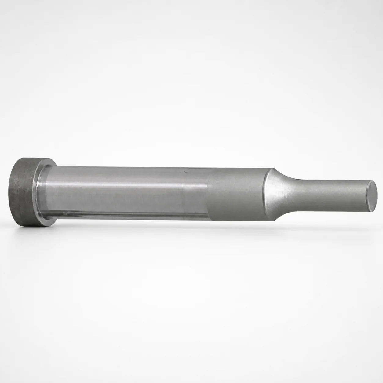
WPC-Treated Shoulder Punches - Single-Stepped
Shoulder punches with a single-stepped shank and WPC surface treatment provide controlled support and reliable punch return in progressive or transfer tooling. The standard shank mounting geometry helps maintain stable alignment during operation.
- Single-stepped shank design for consistent positioning under forming loads
- WPC treated wear-resistant surface for improved sliding performance
- Hardened steel options including SKD11 equivalent, M2 equivalent, and M4 equivalent
- Designed as shoulder punches for die applications requiring compact support
Specifications
8940 configurations available
| Tip shape | Material | Shank diameter D tolerance | B (Tip length) | D (Shank diameter) (mm) | P (Tip dimension) (mm) | L (L dimension) (mm) | LC (Full length alteration) (mm) | LCT (Head thickness tolerance change + total length alteration) (mm) | LMT(Head thickness tolerance change+Full length change) (mm) | PC (Tip dimension alteration) (mm) | R (Tip corner R) (mm) | W (Tip dimension) (mm) | WC (Tip dimension alteration) (mm) | type |
|---|---|---|---|---|---|---|---|---|---|---|---|---|---|---|
| Round | SKH40 Equivalent (Powdered High-Speed Steel) | +0.005/0 | L | 3 | 1 ~ 2.99 | 50 ~ 100 | - | - | - | - | - | - | - | - |
| Round | SKH40 Equivalent (Powdered High-Speed Steel) | +0.005/0 | L | 3 | - | 50 ~ 100 | - | - | - | 0.5 ~ 0.99 | - | - | - | - |
| Round | SKH40 Equivalent (Powdered High-Speed Steel) | +0.005/0 | L | 3 | 1 ~ 2.99 | - | 27 ~ 99.9 | - | - | - | - | - | - | - |
| Round | SKH40 Equivalent (Powdered High-Speed Steel) | +0.005/0 | L | 3 | - | - | 27 ~ 99.9 | - | - | 0.5 ~ 0.99 | - | - | - | - |
| Round | SKH40 Equivalent (Powdered High-Speed Steel) | +0.005/0 | L | 3 | 1 ~ 2.99 | - | - | 27 ~ 99.9 | - | - | - | - | - | - |
| Round | SKH40 Equivalent (Powdered High-Speed Steel) | +0.005/0 | L | 3 | - | - | - | 27 ~ 99.9 | - | 0.5 ~ 0.99 | - | - | - | - |
| Round | SKH40 Equivalent (Powdered High-Speed Steel) | +0.005/0 | L | 3 | 1 ~ 2.99 | - | - | - | 27 ~ 99.9 | - | - | - | - | - |
| Round | SKH40 Equivalent (Powdered High-Speed Steel) | +0.005/0 | L | 3 | - | - | - | - | 27 ~ 99.9 | 0.5 ~ 0.99 | - | - | - | - |
| Round | SKH40 Equivalent (Powdered High-Speed Steel) | +0.005/0 | L | 4 | 1 ~ 3.99 | 50 ~ 100 | - | - | - | - | - | - | - | - |
| Round | SKH40 Equivalent (Powdered High-Speed Steel) | +0.005/0 | L | 4 | - | 50 ~ 100 | - | - | - | 0.5 ~ 0.99 | - | - | - | - |
| Round | SKH40 Equivalent (Powdered High-Speed Steel) | +0.005/0 | L | 4 | 1 ~ 3.99 | - | 27 ~ 99.9 | - | - | - | - | - | - | - |
| Round | SKH40 Equivalent (Powdered High-Speed Steel) | +0.005/0 | L | 4 | - | - | 27 ~ 99.9 | - | - | 0.5 ~ 0.99 | - | - | - | - |
| Round | SKH40 Equivalent (Powdered High-Speed Steel) | +0.005/0 | L | 4 | 1 ~ 3.99 | - | - | 27 ~ 99.9 | - | - | - | - | - | - |
| Round | SKH40 Equivalent (Powdered High-Speed Steel) | +0.005/0 | L | 4 | - | - | - | 27 ~ 99.9 | - | 0.5 ~ 0.99 | - | - | - | - |
| Round | SKH40 Equivalent (Powdered High-Speed Steel) | +0.005/0 | L | 4 | 1 ~ 3.99 | - | - | - | 27 ~ 99.9 | - | - | - | - | - |
| Round | SKH40 Equivalent (Powdered High-Speed Steel) | +0.005/0 | L | 4 | - | - | - | - | 27 ~ 99.9 | 0.5 ~ 0.99 | - | - | - | - |
| Round | SKH40 Equivalent (Powdered High-Speed Steel) | +0.005/0 | L | 5 | 2 ~ 4.99 | 50 ~ 100 | - | - | - | - | - | - | - | - |
| Round | SKH40 Equivalent (Powdered High-Speed Steel) | +0.005/0 | L | 5 | - | 50 ~ 100 | - | - | - | 1 ~ 1.99 | - | - | - | - |
| Round | SKH40 Equivalent (Powdered High-Speed Steel) | +0.005/0 | L | 5 | 2 ~ 4.99 | - | 27 ~ 99.9 | - | - | - | - | - | - | - |
| Round | SKH40 Equivalent (Powdered High-Speed Steel) | +0.005/0 | L | 5 | - | - | 27 ~ 99.9 | - | - | 1 ~ 1.99 | - | - | - | - |
| Round | SKH40 Equivalent (Powdered High-Speed Steel) | +0.005/0 | L | 5 | 2 ~ 4.99 | - | - | 27 ~ 99.9 | - | - | - | - | - | - |
| Round | SKH40 Equivalent (Powdered High-Speed Steel) | +0.005/0 | L | 5 | - | - | - | 27 ~ 99.9 | - | 1 ~ 1.99 | - | - | - | - |
| Round | SKH40 Equivalent (Powdered High-Speed Steel) | +0.005/0 | L | 5 | 2 ~ 4.99 | - | - | - | 27 ~ 99.9 | - | - | - | - | - |
| Round | SKH40 Equivalent (Powdered High-Speed Steel) | +0.005/0 | L | 5 | - | - | - | - | 27 ~ 99.9 | 1 ~ 1.99 | - | - | - | - |
| Round | SKH40 Equivalent (Powdered High-Speed Steel) | +0.005/0 | L | 6 | 2 ~ 5.99 | 50 ~ 100 | - | - | - | - | - | - | - | - |
| Round | SKH40 Equivalent (Powdered High-Speed Steel) | +0.005/0 | L | 6 | - | 50 ~ 100 | - | - | - | 1 ~ 1.99 | - | - | - | - |
| Round | SKH40 Equivalent (Powdered High-Speed Steel) | +0.005/0 | L | 6 | 2 ~ 5.99 | - | 27 ~ 99.9 | - | - | - | - | - | - | - |
| Round | SKH40 Equivalent (Powdered High-Speed Steel) | +0.005/0 | L | 6 | - | - | 27 ~ 99.9 | - | - | 1 ~ 1.99 | - | - | - | - |
| Round | SKH40 Equivalent (Powdered High-Speed Steel) | +0.005/0 | L | 6 | 2 ~ 5.99 | - | - | 27 ~ 99.9 | - | - | - | - | - | - |
| Round | SKH40 Equivalent (Powdered High-Speed Steel) | +0.005/0 | L | 6 | - | - | - | 27 ~ 99.9 | - | 1 ~ 1.99 | - | - | - | - |
| Round | SKH40 Equivalent (Powdered High-Speed Steel) | +0.005/0 | L | 6 | 2 ~ 5.99 | - | - | - | 27 ~ 99.9 | - | - | - | - | - |
| Round | SKH40 Equivalent (Powdered High-Speed Steel) | +0.005/0 | L | 6 | - | - | - | - | 27 ~ 99.9 | 1 ~ 1.99 | - | - | - | - |
| Round | SKH40 Equivalent (Powdered High-Speed Steel) | +0.005/0 | L | 8 | 3 ~ 7.99 | 50 ~ 100 | - | - | - | - | - | - | - | - |
| Round | SKH40 Equivalent (Powdered High-Speed Steel) | +0.005/0 | L | 8 | - | 50 ~ 100 | - | - | - | 1.5 ~ 2.99 | - | - | - | - |
| Round | SKH40 Equivalent (Powdered High-Speed Steel) | +0.005/0 | L | 8 | 3 ~ 7.99 | - | 27 ~ 99.9 | - | - | - | - | - | - | - |
| Round | SKH40 Equivalent (Powdered High-Speed Steel) | +0.005/0 | L | 8 | - | - | 27 ~ 99.9 | - | - | 1.5 ~ 2.99 | - | - | - | - |
| Round | SKH40 Equivalent (Powdered High-Speed Steel) | +0.005/0 | L | 8 | 3 ~ 7.99 | - | - | 27 ~ 99.9 | - | - | - | - | - | - |
| Round | SKH40 Equivalent (Powdered High-Speed Steel) | +0.005/0 | L | 8 | - | - | - | 27 ~ 99.9 | - | 1.5 ~ 2.99 | - | - | - | - |
| Round | SKH40 Equivalent (Powdered High-Speed Steel) | +0.005/0 | L | 8 | 3 ~ 7.99 | - | - | - | 27 ~ 99.9 | - | - | - | - | - |
| Round | SKH40 Equivalent (Powdered High-Speed Steel) | +0.005/0 | L | 8 | - | - | - | - | 27 ~ 99.9 | 1.5 ~ 2.99 | - | - | - | - |
| Round | SKH40 Equivalent (Powdered High-Speed Steel) | +0.005/0 | L | 10 | 3 ~ 9.99 | 50 ~ 100 | - | - | - | - | - | - | - | - |
| Round | SKH40 Equivalent (Powdered High-Speed Steel) | +0.005/0 | L | 10 | - | 50 ~ 100 | - | - | - | 1.5 ~ 2.99 | - | - | - | - |
| Round | SKH40 Equivalent (Powdered High-Speed Steel) | +0.005/0 | L | 10 | 3 ~ 9.99 | - | 27 ~ 99.9 | - | - | - | - | - | - | - |
| Round | SKH40 Equivalent (Powdered High-Speed Steel) | +0.005/0 | L | 10 | - | - | 27 ~ 99.9 | - | - | 1.5 ~ 2.99 | - | - | - | - |
| Round | SKH40 Equivalent (Powdered High-Speed Steel) | +0.005/0 | L | 10 | 3 ~ 9.99 | - | - | 27 ~ 99.9 | - | - | - | - | - | - |
| Round | SKH40 Equivalent (Powdered High-Speed Steel) | +0.005/0 | L | 10 | - | - | - | 27 ~ 99.9 | - | 1.5 ~ 2.99 | - | - | - | - |
| Round | SKH40 Equivalent (Powdered High-Speed Steel) | +0.005/0 | L | 10 | 3 ~ 9.99 | - | - | - | 27 ~ 99.9 | - | - | - | - | - |
| Round | SKH40 Equivalent (Powdered High-Speed Steel) | +0.005/0 | L | 10 | - | - | - | - | 27 ~ 99.9 | 1.5 ~ 2.99 | - | - | - | - |
| Round | SKH40 Equivalent (Powdered High-Speed Steel) | +0.005/0 | L | 13 | 6 ~ 12.99 | 50 ~ 100 | - | - | - | - | - | - | - | - |
| Round | SKH40 Equivalent (Powdered High-Speed Steel) | +0.005/0 | L | 13 | - | 50 ~ 100 | - | - | - | 3 ~ 5.99 | - | - | - | - |
Product Guide
Application Scenarios+
Shoulder punches with a single-stepped shank are commonly used in progressive and transfer die sets where the punch must deliver support and return forces with tight positional consistency.
- Automotive connector and terminal forming tools: the shoulder geometry provides controlled load transfer into the die, helping maintain stable alignment under repeated forming cycles. The WPC-treated surface supports smoother sliding at the die interface.
- Electronics housing and bracket dies: the compact, single-step shank mounting helps locate the punch consistently, improving repeatability when forming small features with varying tip shapes (round/rectangle/oblong).
- General-purpose metal stamping for small parts: WPC wear resistance reduces tooling surface degradation, supporting reliable punch return and longer productive life in high-cycle applications.
This variant is suited because the WPC surface treatment improves wear and sliding performance, while the single-stepped design supports consistent positioning during forming loads.
Material & Process Details+
This series is offered in hardened steel equivalents, chosen to balance wear resistance and toughness based on load and cycle rate.
- SKH40 equivalent (powder high-speed steel): typically used when higher hot hardness and wear resistance are beneficial for demanding punch operation.
- SKH51 equivalent (M2): an AISI M2-class high-speed steel option, known for strong wear resistance with a toughness trade-off versus D2-class steels.
- SKD11 equivalent (D2): an AISI D2 equivalent for excellent wear resistance, often selected when longer service life on abrasive or harder work materials is required.
All variants are supplied as hardened steel options and matched with the WPC surface treatment to enhance sliding performance. The appropriate choice depends on your desired wear resistance versus toughness margin for the specific tip shape and dimensions.
Sizing & Selection Guide+
Selection starts with matching the punch shank and head geometry to the die and guide system that will hold the punch during forming.
- Shank diameter (D): choose from 3–25 mm. The shank tolerance is +0.005/0, m5, so verify your die insert bore/guide requirement to achieve the intended clearance or fit.
- Tip size (P): select 1–18 mm based on the required forming feature size and die opening.
- Tip length (B): choose the appropriate category (L, S, X) for the die support length and knockout/stripping behavior.
- Overall length (L) and alterations: L is specified across multiple ranges (e.g., 50–100, 60–100, 40–100, 70–100, and 40–100 mm). Use LC (26–47 mm), LCT, and LMT (26–47 mm) to confirm the required length alteration and tolerance change constraints.
When ordering, ensure the chosen tip corner radius R = 0.15 mm (as specified) and the tip dimension alterations (PC 0.5–9 mm, WC 0.8–3 mm) align with the die profile to prevent premature wear or misalignment.
Frequently Asked Questions
Which WPC-treated shoulder punch steel equivalent should I select: SKD11 (D2) vs SKH51 (M2) vs SKH40?+
Choose SKD11 equivalent (D2) when you prioritize wear resistance for longer life in abrasive or harder work materials. Select SKH51 equivalent (M2) (AISI M2-class) when you want strong wear resistance with a different toughness balance suited for demanding punch cycles. Use SKH40 equivalent (powder high-speed steel) when your application benefits from high-speed-steel performance characteristics. The final decision should consider your cycle count, load, and acceptable toughness-to-wear trade-offs.
How do I verify compatibility with my guide or die bore given the shank diameter tolerance (+0.005/0, m5)?+
The shank diameter D is specified from 3–25 mm with tolerance +0.005/0, m5. Confirm that your die bore or guide hole is dimensioned to provide the intended clearance/fit for stable alignment under forming loads. Because the tolerance is asymmetric (+0.005/0), plan for the maximum material condition when calculating clearance.
What tip geometry options are available and how should I choose among round, rectangle, oblong, and double-flatted round?+
Tip shapes include Round, Rectangle, Oblong, Double Flatted Round, and Radius Rectangle. Pick the shape that matches the required forming feature and die opening profile, then size the tip dimensions using P (1–18 mm) and the tip width W (1–6 mm) plus the specified alterations (PC 0.5–9 mm, WC 0.8–3 mm). The specified corner radius is R = 0.15 mm for the offered configuration.
How do I select overall length (L) and length alteration values (LC / LCT / LMT) for a shoulder punch?+
Overall length L is offered across multiple ranges (e.g., 50–100, 60–100, 40–100, 70–100, and 40–100 mm, as listed). Use LC (26–47 mm) and the tolerance/alteration parameters LCT and LMT (each 26–47 mm) to meet the die stack-up and required total length change constraints. Ensure the chosen B type (L, S, or X) aligns with the required support length in the die.
What should I consider when choosing tip length (B: L/S/X) together with tip dimension P (1–18 mm)?+
Tip length B (options L, S, X) controls the effective punch engagement/support length in the die. Pair it with P (tip dimension 1–18 mm) and width W (1–6 mm) so the punch profile matches the forming pocket and avoids edge loading. If your design requires profile adjustments, apply the allowed alterations PC (0.5–9 mm) and WC (0.8–3 mm) within the specified configuration limits.
Related Products






Need Custom Specifications?
Our engineering team can help with custom configurations, material selection, and volume pricing.