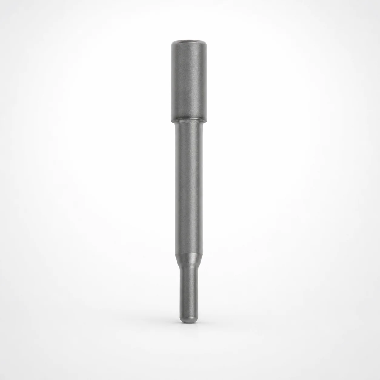
HW-PHTAL Round Stopper Punches
Round stopper punches (HW-PHTAL) provide heavy-load, single-stepped punching performance with a round tip for reliable forming. Built for durability, they help maintain consistent punch action in demanding production.
- Single-stepped round tip design supports robust force handling in tough operations
- Powder high-speed steel equivalent SKH40 for wear resistance under cyclic loading
- Engineered for repeatable punch fit using controlled overall geometry changes
- HW-PHTAL coating option for improved surface performance in production environments
Specifications
168 configurations available
| D (Shank diameter) (mm) | P (Tip dimension) (mm) | L (L dimension) (mm) | B (Tip length) (mm) | LC (Full length alteration) (mm) | LCT (Head thickness tolerance change + total length alteration) (mm) | T (Head thickness) (mm) | TC (Head thickness change) (mm) | Tip length change [BC] (mm) | type |
|---|---|---|---|---|---|---|---|---|---|
| 4 | 1 ~ 2 | 40 ~ 50 | 2 ~ 6 | - | - | 13 ~ 25 | - | - | - |
| 4 | 1 ~ 2 | 40 ~ 50 | - | - | - | 13 ~ 25 | - | 2.1 ~ 40 | - |
| 4 | 1 ~ 2 | 40 ~ 50 | 2 ~ 6 | - | - | - | 13.1 ~ 24.9 | - | - |
| 4 | 1 ~ 2 | 40 ~ 50 | - | - | - | - | 13.1 ~ 24.9 | 2.1 ~ 40 | - |
| 4 | 1 ~ 2 | - | 2 ~ 6 | 40 ~ 50 | - | 13 ~ 25 | - | - | - |
| 4 | 1 ~ 2 | - | - | 40 ~ 50 | - | 13 ~ 25 | - | 2.1 ~ 40 | - |
| 4 | 1 ~ 2 | - | 2 ~ 6 | 40 ~ 50 | - | - | 13.1 ~ 24.9 | - | - |
| 4 | 1 ~ 2 | - | - | 40 ~ 50 | - | - | 13.1 ~ 24.9 | 2.1 ~ 40 | - |
| 4 | 1 ~ 2 | - | 2 ~ 6 | - | 40 ~ 50 | 13 ~ 25 | - | - | - |
| 4 | 1 ~ 2 | - | - | - | 40 ~ 50 | 13 ~ 25 | - | 2.1 ~ 40 | - |
| 4 | 1 ~ 2 | - | 2 ~ 6 | - | 40 ~ 50 | - | 13.1 ~ 24.9 | - | - |
| 4 | 1 ~ 2 | - | - | - | 40 ~ 50 | - | 13.1 ~ 24.9 | 2.1 ~ 40 | - |
| 5 | 1 ~ 3 | 40 ~ 60 | 2 ~ 8 | - | - | 13 ~ 25 | - | - | - |
| 5 | 1 ~ 3 | 40 ~ 60 | - | - | - | 13 ~ 25 | - | 2.1 ~ 40 | - |
| 5 | 1 ~ 3 | 40 ~ 60 | 2 ~ 8 | - | - | - | 13.1 ~ 24.9 | - | - |
| 5 | 1 ~ 3 | 40 ~ 60 | - | - | - | - | 13.1 ~ 24.9 | 2.1 ~ 40 | - |
| 5 | 1 ~ 3 | - | 2 ~ 8 | 40 ~ 60 | - | 13 ~ 25 | - | - | - |
| 5 | 1 ~ 3 | - | - | 40 ~ 60 | - | 13 ~ 25 | - | 2.1 ~ 40 | - |
| 5 | 1 ~ 3 | - | 2 ~ 8 | 40 ~ 60 | - | - | 13.1 ~ 24.9 | - | - |
| 5 | 1 ~ 3 | - | - | 40 ~ 60 | - | - | 13.1 ~ 24.9 | 2.1 ~ 40 | - |
| 5 | 1 ~ 3 | - | 2 ~ 8 | - | 40 ~ 60 | 13 ~ 25 | - | - | - |
| 5 | 1 ~ 3 | - | - | - | 40 ~ 60 | 13 ~ 25 | - | 2.1 ~ 40 | - |
| 5 | 1 ~ 3 | - | 2 ~ 8 | - | 40 ~ 60 | - | 13.1 ~ 24.9 | - | - |
| 5 | 1 ~ 3 | - | - | - | 40 ~ 60 | - | 13.1 ~ 24.9 | 2.1 ~ 40 | - |
| 6 | 1.5 ~ 4 | 40 ~ 70 | 2 ~ 13 | - | - | 13 ~ 25 | - | - | - |
| 6 | 1.5 ~ 4 | 40 ~ 70 | - | - | - | 13 ~ 25 | - | 2.1 ~ 40 | - |
| 6 | 1.5 ~ 4 | 40 ~ 70 | 2 ~ 13 | - | - | - | 13.1 ~ 24.9 | - | - |
| 6 | 1.5 ~ 4 | 40 ~ 70 | - | - | - | - | 13.1 ~ 24.9 | 2.1 ~ 40 | - |
| 6 | 1.5 ~ 4 | - | 2 ~ 13 | 40 ~ 70 | - | 13 ~ 25 | - | - | - |
| 6 | 1.5 ~ 4 | - | - | 40 ~ 70 | - | 13 ~ 25 | - | 2.1 ~ 40 | - |
| 6 | 1.5 ~ 4 | - | 2 ~ 13 | 40 ~ 70 | - | - | 13.1 ~ 24.9 | - | - |
| 6 | 1.5 ~ 4 | - | - | 40 ~ 70 | - | - | 13.1 ~ 24.9 | 2.1 ~ 40 | - |
| 6 | 1.5 ~ 4 | - | 2 ~ 13 | - | 40 ~ 70 | 13 ~ 25 | - | - | - |
| 6 | 1.5 ~ 4 | - | - | - | 40 ~ 70 | 13 ~ 25 | - | 2.1 ~ 40 | - |
| 6 | 1.5 ~ 4 | - | 2 ~ 13 | - | 40 ~ 70 | - | 13.1 ~ 24.9 | - | - |
| 6 | 1.5 ~ 4 | - | - | - | 40 ~ 70 | - | 13.1 ~ 24.9 | 2.1 ~ 40 | - |
| 8 | 2 ~ 6 | 40 ~ 70 | 2 ~ 13 | - | - | 13 ~ 25 | - | - | - |
| 8 | 2 ~ 6 | 40 ~ 70 | - | - | - | 13 ~ 25 | - | 2.1 ~ 40 | - |
| 8 | 2 ~ 6 | 40 ~ 70 | 2 ~ 13 | - | - | - | 13.1 ~ 24.9 | - | - |
| 8 | 2 ~ 6 | 40 ~ 70 | - | - | - | - | 13.1 ~ 24.9 | 2.1 ~ 40 | - |
| 8 | 2 ~ 6 | - | 2 ~ 13 | 40 ~ 70 | - | 13 ~ 25 | - | - | - |
| 8 | 2 ~ 6 | - | - | 40 ~ 70 | - | 13 ~ 25 | - | 2.1 ~ 40 | - |
| 8 | 2 ~ 6 | - | 2 ~ 13 | 40 ~ 70 | - | - | 13.1 ~ 24.9 | - | - |
| 8 | 2 ~ 6 | - | - | 40 ~ 70 | - | - | 13.1 ~ 24.9 | 2.1 ~ 40 | - |
| 8 | 2 ~ 6 | - | 2 ~ 13 | - | 40 ~ 70 | 13 ~ 25 | - | - | - |
| 8 | 2 ~ 6 | - | - | - | 40 ~ 70 | 13 ~ 25 | - | 2.1 ~ 40 | - |
| 8 | 2 ~ 6 | - | 2 ~ 13 | - | 40 ~ 70 | - | 13.1 ~ 24.9 | - | - |
| 8 | 2 ~ 6 | - | - | - | 40 ~ 70 | - | 13.1 ~ 24.9 | 2.1 ~ 40 | - |
| 10 | 3 ~ 8 | 40 ~ 70 | 2 ~ 13 | - | - | 13 ~ 25 | - | - | - |
| 10 | 3 ~ 8 | 40 ~ 70 | - | - | - | 13 ~ 25 | - | 2.1 ~ 40 | - |
Product Guide
Application Scenarios+
Round stopper punches are used in injection mold tooling where a controlled stop and forming action is required during the punching/blanking step. The single-stepped round tip helps concentrate and stabilize contact, making it suitable for parts that demand consistent material shaping across many cycles.
Common scenarios include automotive connector and bracket molds, where the punch must maintain repeatable engagement under heavy loads. The durable wear-focused steel selection and optional surface coating support stable punch behavior during high-throughput production.
They are also used in appliance and consumer electronics housings to support reliable forming of features that require a predictable stop position. Engineers can select from the available D (4–25 mm) and tip parameters to match the required cavity/core clearances and punching geometry.
- Heavy-load, single-stepped action for tough operations
- Round tip geometry for dependable forming contact
- Coating option (HW-PHTAL) for improved surface performance
Material & Process Details+
These punches are manufactured from SKH40 high-speed steel (powder HSS equivalent), which is selected for its strong wear resistance under cyclic loading. For applications with repeated impact and sliding at the tip, the grade supports stable cutting/punching performance while helping reduce dimensional drift from abrasive wear.
Depending on the supplier standard, SKH40 HSS punches are typically heat-treated for high hardness (commonly in the ~HRC 60–66 range for HSS tools) and balanced for toughness vs. wear: higher hardness improves wear life, while excessive hardening can reduce resistance to shock. In practice, the design’s single-stepped contact and controlled geometry help manage toughness demands.
- SKH40 (powder HSS): high wear resistance for long-run punching
- HW-PHTAL coating option: improved surface performance in production environments
If compared to lower-wear steels, SKH40 offers superior edge retention; compared with more shock-tough tool steels, HSS may require careful parameter control to avoid chipping under severe impact.
Sizing & Selection Guide+
To select the correct round stopper punch, start by matching the shank diameter D (4–25 mm) to the guide/bushing requirement in your mold. Next, choose the tip dimension P (1–13 mm) and B (tip length) (2–6 mm, 2–8 mm, or 2–13 mm) so the round tip engages the material with the intended stop geometry.
The working length is controlled by the L (40–50 mm, 40–60 mm, or 40–70 mm) and the corresponding LC (full length alteration) (40–50 / 40–60 / 40–70). Use the offered head and length alteration options to align the punch seating depth and total stack-up with your cavity/core layout.
- Match D for fit in mold guiding features
- Match P and B for stop/contact geometry
- Match L and LC for overall reach to the forming surface
Note the fixed T (head thickness) = 13–25 mm and the provided alteration ranges; this family supports multiple geometry variants rather than a single fixed length. Where length alteration states apply, maintain consistent stack-up tolerances to prevent variation in stop position during production.
Frequently Asked Questions
How do I choose the shank diameter D for stopper punch fit in my mold guide?+
Which tip parameters control the stop/contact geometry: P, B, or head thickness T?+
What length options (L and LC) should I use to match my cavity/core stack-up?+
Is HW-PHTAL suitable when the tool sees high cyclic loading and sliding at the punch tip?+
What should I verify about head thickness variation TC when selecting this punch family?+
Related Products






Need Custom Specifications?
Our engineering team can help with custom configurations, material selection, and volume pricing.