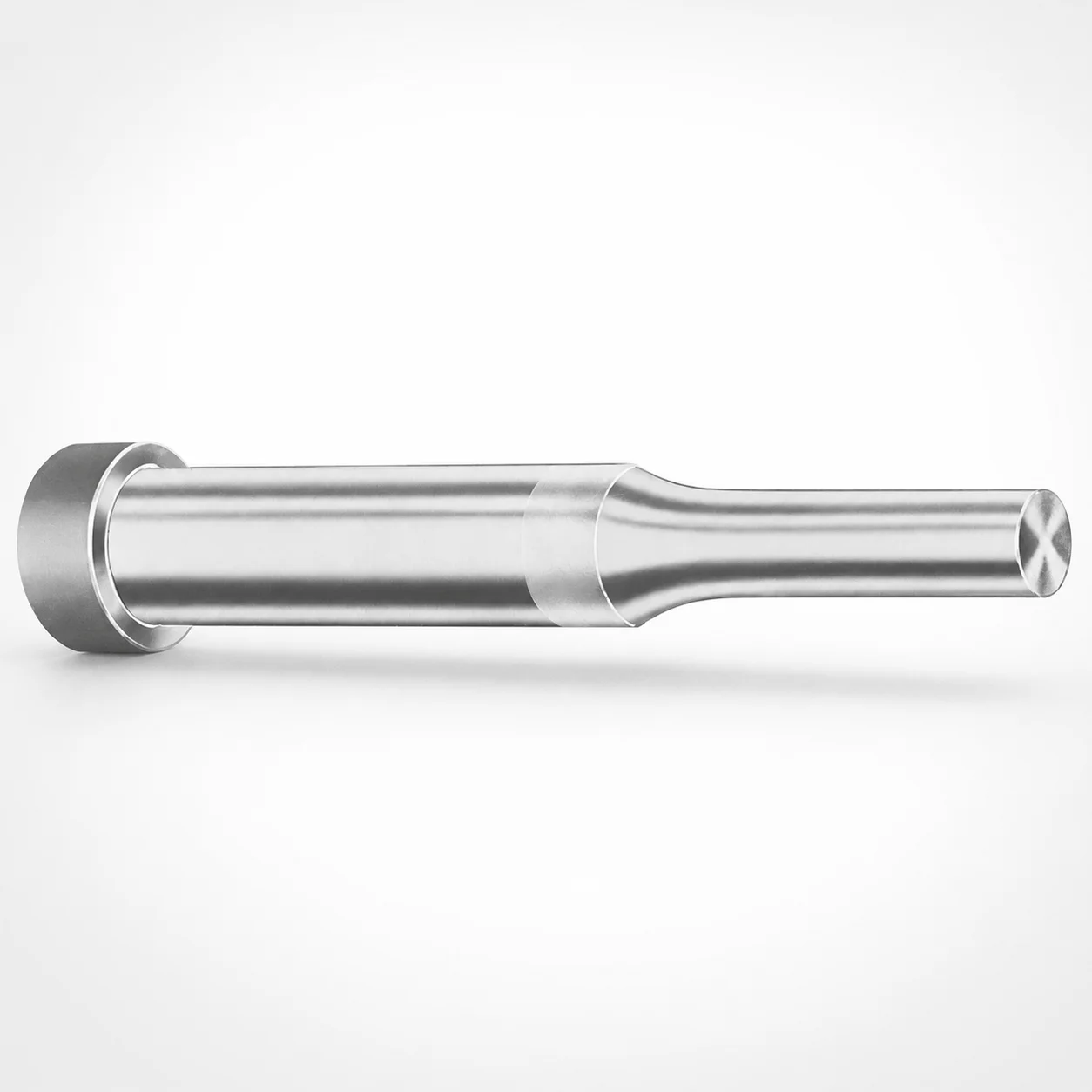
Regular Punches - Metric, XNM Coating
Regular Punches - Metric, XNM Coating are engineered by DAYTON for consistent punching performance in precision dies. The XNM coating helps improve wear resistance while the Dayton LAMINA part numbering format simplifies specification and ordering.
- XNM coating design supports stable tool life in repeated blanking cycles
- Metric regular punches for general die applications across industrial forming
- Tip shapes include X, R, K, O, H, L, J, N, V, Z for process flexibility
- Dayton LAMINA standardized part number format streamlines procurement documentation
Specifications
318 configurations available
| Tip shape | Material | D (Shank dia.) (mm) | L1 (Point Length) (mm) | L (Length) (mm) | P Dimension (mm) | W Dimension (mm) | R Dimension (mm) |
|---|---|---|---|---|---|---|---|
| H | M2 | 04 | 8 ~ 13 | 40 ~ 100 | 1.3 ~ 3.95 | 1.3 ~ 1.59 | - |
| H | M2 | 04 | 8 ~ 13 | 40 ~ 100 | 1.3 ~ 3.95 | 1.6 ~ 3.95 | - |
| H | PS | 04 | 8 ~ 13 | 40 ~ 100 | 1.3 ~ 3.95 | 1.3 ~ 1.59 | - |
| H | PS | 04 | 8 ~ 13 | 40 ~ 100 | 1.3 ~ 3.95 | 1.6 ~ 3.95 | - |
| H | M2 | 05 | 13 ~ 19 | 40 ~ 100 | 1.6 ~ 4.95 | 1.6 ~ 4.95 | - |
| H | PS | 05 | 13 ~ 19 | 40 ~ 100 | 1.6 ~ 4.95 | 1.6 ~ 4.95 | - |
| H | M2 | 06 | 13 ~ 19 | 40 ~ 100 | 1.6 ~ 5.95 | 1.6 ~ 5.95 | - |
| H | PS | 06 | 13 ~ 19 | 40 ~ 100 | 1.6 ~ 5.95 | 1.6 ~ 5.95 | - |
| H | M2 | 08 | 19 ~ 25 | 50 ~ 100 | 2.5 ~ 7.95 | 2.5 ~ 7.95 | - |
| H | PS | 08 | 19 ~ 25 | 50 ~ 100 | 2.5 ~ 7.95 | 2.5 ~ 7.95 | - |
| H | M2 | 10 | 19 ~ 25 | 50 ~ 100 | 3.2 ~ 9.95 | 3.2 ~ 9.95 | - |
| H | PS | 10 | 19 ~ 25 | 50 ~ 100 | 3.2 ~ 9.95 | 3.2 ~ 9.95 | - |
| H | M2 | 13 | 19 ~ 25 | 50 ~ 100 | 4 ~ 12.95 | 4 ~ 4.49 | - |
| H | M2 | 13 | 19 ~ 25 | 50 ~ 100 | 4 ~ 12.95 | 4.5 ~ 12.95 | - |
| H | PS | 13 | 19 ~ 25 | 50 ~ 100 | 4 ~ 12.95 | 4 ~ 4.49 | - |
| H | PS | 13 | 19 ~ 25 | 50 ~ 100 | 4 ~ 12.95 | 4.5 ~ 12.95 | - |
| H | M2 | 16 | 19 ~ 25 | 50 ~ 100 | 6 ~ 15.95 | 6 ~ 15.95 | - |
| H | PS | 16 | 19 ~ 25 | 50 ~ 100 | 6 ~ 15.95 | 6 ~ 15.95 | - |
| H | M2 | 20 | 19 ~ 25 | 56 ~ 100 | 6 ~ 19.95 | 6 ~ 7.99 | - |
| H | M2 | 20 | 19 ~ 25 | 56 ~ 100 | 6 ~ 19.95 | 8 ~ 19.95 | - |
| H | PS | 20 | 19 ~ 25 | 56 ~ 100 | 6 ~ 19.95 | 6 ~ 7.99 | - |
| H | PS | 20 | 19 ~ 25 | 56 ~ 100 | 6 ~ 19.95 | 8 ~ 19.95 | - |
| H | M2 | 25 | 19 ~ 25 | 56 ~ 100 | 6 ~ 24.95 | 6 ~ 8.99 | - |
| H | M2 | 25 | 19 ~ 25 | 56 ~ 100 | 6 ~ 24.95 | 9 ~ 24.95 | - |
| H | PS | 25 | 19 ~ 25 | 56 ~ 100 | 6 ~ 24.95 | 6 ~ 8.99 | - |
| H | PS | 25 | 19 ~ 25 | 56 ~ 100 | 6 ~ 24.95 | 9 ~ 24.95 | - |
| H | M2 | 32 | 25 ~ 30 | 63 ~ 100 | 7.2 ~ 31.95 | 7.2 ~ 9.99 | - |
| H | M2 | 32 | 25 ~ 30 | 63 ~ 100 | 7.2 ~ 31.95 | 10 ~ 31.95 | - |
| H | PS | 32 | 25 ~ 30 | 63 ~ 100 | 7.2 ~ 31.95 | 7.2 ~ 9.99 | - |
| H | PS | 32 | 25 ~ 30 | 63 ~ 100 | 7.2 ~ 31.95 | 10 ~ 31.95 | - |
| J | M2 | 04 | 8 ~ 13 | 40 ~ 100 | 1.3 ~ 3.95 | 1.3 ~ 1.59 | - |
| J | M2 | 04 | 8 ~ 13 | 40 ~ 100 | 1.3 ~ 3.95 | 1.6 ~ 3.95 | - |
| J | PS | 04 | 8 ~ 13 | 40 ~ 100 | 1.3 ~ 3.95 | 1.3 ~ 1.59 | - |
| J | PS | 04 | 8 ~ 13 | 40 ~ 100 | 1.3 ~ 3.95 | 1.6 ~ 3.95 | - |
| J | M2 | 05 | 13 ~ 19 | 40 ~ 100 | 1.6 ~ 4.95 | 1.6 ~ 4.95 | - |
| J | PS | 05 | 13 ~ 19 | 40 ~ 100 | 1.6 ~ 4.95 | 1.6 ~ 4.95 | - |
| J | M2 | 06 | 13 ~ 19 | 40 ~ 100 | 1.6 ~ 5.95 | 1.6 ~ 5.95 | - |
| J | PS | 06 | 13 ~ 19 | 40 ~ 100 | 1.6 ~ 5.95 | 1.6 ~ 5.95 | - |
| J | M2 | 08 | 19 ~ 25 | 50 ~ 100 | 2.5 ~ 7.95 | 2.5 ~ 7.95 | - |
| J | PS | 08 | 19 ~ 25 | 50 ~ 100 | 2.5 ~ 7.95 | 2.5 ~ 7.95 | - |
| J | M2 | 10 | 19 ~ 25 | 50 ~ 100 | 3.2 ~ 9.95 | 3.2 ~ 9.95 | - |
| J | PS | 10 | 19 ~ 25 | 50 ~ 100 | 3.2 ~ 9.95 | 3.2 ~ 9.95 | - |
| J | M2 | 13 | 19 ~ 25 | 50 ~ 100 | 4 ~ 12.95 | 4 ~ 4.49 | - |
| J | M2 | 13 | 19 ~ 25 | 50 ~ 100 | 4 ~ 12.95 | 4.5 ~ 12.95 | - |
| J | PS | 13 | 19 ~ 25 | 50 ~ 100 | 4 ~ 12.95 | 4 ~ 4.49 | - |
| J | PS | 13 | 19 ~ 25 | 50 ~ 100 | 4 ~ 12.95 | 4.5 ~ 12.95 | - |
| J | M2 | 16 | 19 ~ 25 | 50 ~ 100 | 6 ~ 15.95 | 6 ~ 15.95 | - |
| J | PS | 16 | 19 ~ 25 | 50 ~ 100 | 6 ~ 15.95 | 6 ~ 15.95 | - |
| J | M2 | 20 | 19 ~ 25 | 56 ~ 100 | 6 ~ 19.95 | 6 ~ 7.99 | - |
| J | M2 | 20 | 19 ~ 25 | 56 ~ 100 | 6 ~ 19.95 | 8 ~ 19.95 | - |
Product Guide
Application Scenarios+
Regular metric punches with XNM coating are used in injection tooling where precise blanking and piercing are required inside progressive or fine-blanking die sets. The coating is selected to support stable tool life during repeated cycles, helping maintain edge condition and dimensional consistency of the produced features.
Common scenarios include:
- Automotive connector and terminal dies: metric shank diameters from 4 to 32 mm and multiple tip shapes (e.g., X, R, K, O, H, L, J, N, V, Z) support forming of different hole or slot geometries while reducing wear-driven pitch and burr growth.
- Industrial electronic and bracket components: varying point lengths (8–13, 13–19, 19–25, 25–30 mm) and punch lengths (40–100 to 63–100 mm) allow alignment with stripper/guide stack-up and reach requirements for clean piercing.
- General metal forming for housings and brackets: the availability of material options (M2 and PS) lets designers match hardness and toughness needs to the expected wear/impact balance.
Material & Process Details+
This punch series is offered in two material options: M2 and PS, with XNM coating applied for wear reduction during repeated blanking. For engineers targeting high hardness and abrasion resistance, M2 is a high-speed steel selection typically used where tool life under sliding/wiping contact is critical; it balances wear resistance with sufficient toughness for punching operations.
- M2: suited for long-running blanking due to strong wear performance under repeated cycles.
- PS: an alternative material option for designs that require different toughness/response to loading while still benefiting from XNM coating’s friction and wear control.
Heat treatment state is not specified in the provided metadata, so hardness (HRC) and exact tempering/nitriding details cannot be stated here. When finalizing the die build, verify the supplier’s hardness/treatment record per part number, especially if multiple materials (M2 vs. PS) are being compared for tool life and edge retention.
Sizing & Selection Guide+
Select dimensions by matching the punch geometry to the die cavity/core opening and the required piercing depth/reach. Start with the shank diameter D in the range 4 ~ 32 mm, ensuring it fits the guide or bushing bore used in your punch holder system. Choose the tip shape (H, J, K, L, N, O, R, V, X, Y, Z) to match the desired cut profile and edge strength for your feature geometry.
- Point length (L1): pick from 8–13, 13–19, 19–25, 25–30 mm based on the distance from punch contact to where clearance or backing begins in the die stack.
- Punch length (L): choose a range that covers your stripper/holder and full stroke requirement (available ranges include 40–100, 50–100, 56–100, 63–100 mm).
- Feature-related dimensions: set P (0.8 ~ 10 mm) and W (1.3 ~ 10 mm) according to the required contact/cut parameters for the selected tip shape.
Where tight fit is required, confirm the guide/bushing clearance and any published tolerances for the chosen part number; tolerance data is not provided in the metadata.
Frequently Asked Questions
Which tip shapes are available for DAYTON regular punches in this series, and how do they help with different cut profiles?+
How do I choose between M2 and PS material for wear and toughness in XNM-coated punches?+
What shank diameter (D) range is supported, and how does it affect guide fitting?+
How should I select point length (L1) and total punch length (L) from the available ranges?+
What are the available ranges for P and W dimensions, and are R dimensions adjustable?+
Related Products






Need Custom Specifications?
Our engineering team can help with custom configurations, material selection, and volume pricing.