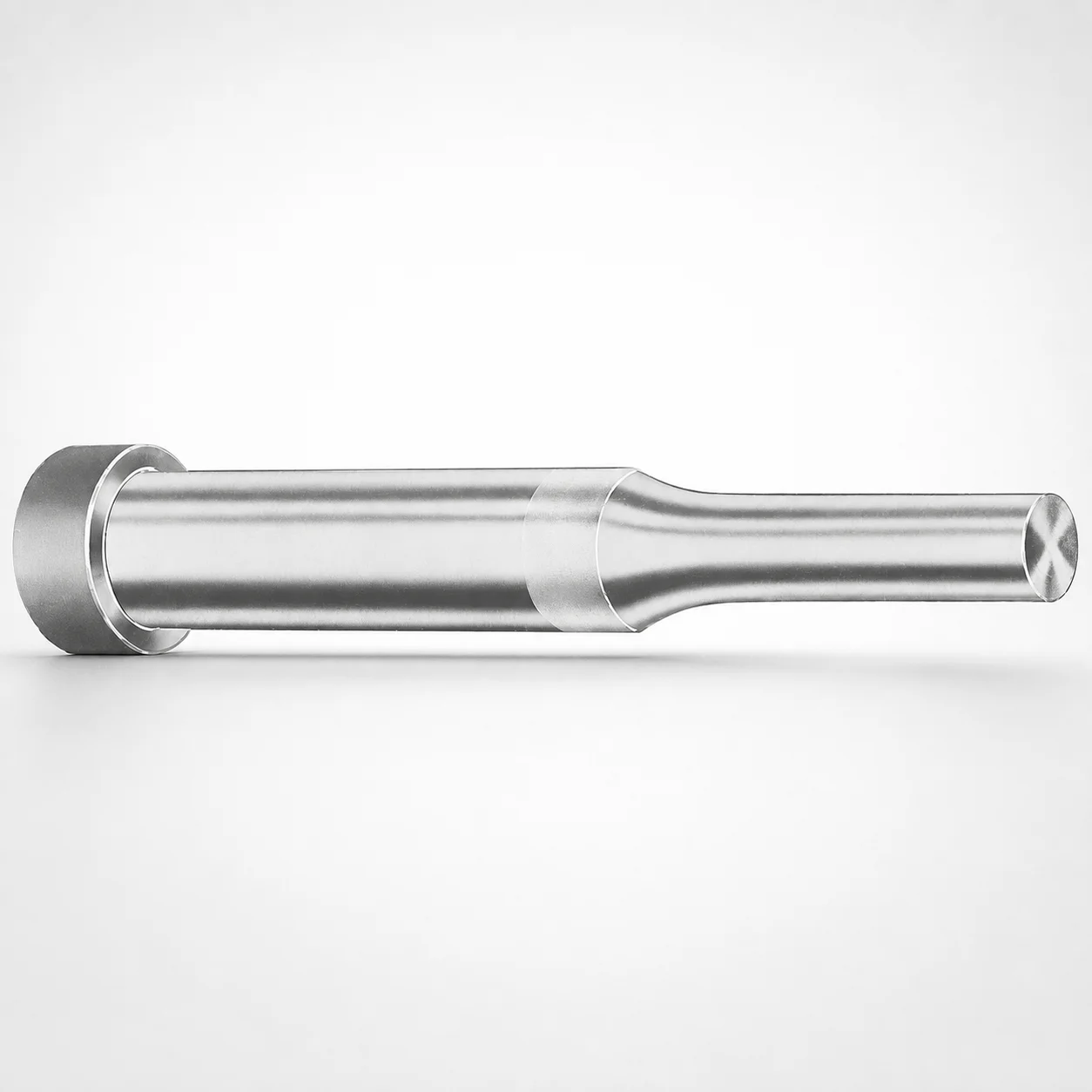
Regular Punches - Metric, XNAD Coating
Regular Punches - Metric, XNAD Coating from DAYTON are designed for reliable blanking and punching in production molds, combining a standardized geometry with a wear-oriented coating system. They help maintain punch performance and consistent transfer during repeated cycles.
- XNAD coating for improved wear resistance during frequent punching cycles
- Available tip shapes (X, R, K, O, H, L, J, N, V, Y, Z) to match die requirements
- Material options include PS or M2 for selecting appropriate tool hardness
- Supports metric shank diameters and point lengths for flexible mold builds
Specifications
318 configurations available
| Tip shape | Material | D (Shank dia.) (mm) | L1 (Point Length) (mm) | L (Length) (mm) | P Dimension (mm) | W Dimension (mm) | R Dimension (mm) |
|---|---|---|---|---|---|---|---|
| H | M2 | 04 | 8 ~ 13 | 40 ~ 100 | 1.3 ~ 3.95 | 1.3 ~ 1.59 | - |
| H | M2 | 04 | 8 ~ 13 | 40 ~ 100 | 1.3 ~ 3.95 | 1.6 ~ 3.95 | - |
| H | PS | 04 | 8 ~ 13 | 40 ~ 100 | 1.3 ~ 3.95 | 1.3 ~ 1.59 | - |
| H | PS | 04 | 8 ~ 13 | 40 ~ 100 | 1.3 ~ 3.95 | 1.6 ~ 3.95 | - |
| H | M2 | 05 | 13 ~ 19 | 40 ~ 100 | 1.6 ~ 4.95 | 1.6 ~ 4.95 | - |
| H | PS | 05 | 13 ~ 19 | 40 ~ 100 | 1.6 ~ 4.95 | 1.6 ~ 4.95 | - |
| H | M2 | 06 | 13 ~ 19 | 40 ~ 100 | 1.6 ~ 5.95 | 1.6 ~ 5.95 | - |
| H | PS | 06 | 13 ~ 19 | 40 ~ 100 | 1.6 ~ 5.95 | 1.6 ~ 5.95 | - |
| H | M2 | 08 | 19 ~ 25 | 50 ~ 100 | 2.5 ~ 7.95 | 2.5 ~ 7.95 | - |
| H | PS | 08 | 19 ~ 25 | 50 ~ 100 | 2.5 ~ 7.95 | 2.5 ~ 7.95 | - |
| H | M2 | 10 | 19 ~ 25 | 50 ~ 100 | 3.2 ~ 9.95 | 3.2 ~ 9.95 | - |
| H | PS | 10 | 19 ~ 25 | 50 ~ 100 | 3.2 ~ 9.95 | 3.2 ~ 9.95 | - |
| H | M2 | 13 | 19 ~ 25 | 50 ~ 100 | 4 ~ 12.95 | 4 ~ 4.49 | - |
| H | M2 | 13 | 19 ~ 25 | 50 ~ 100 | 4 ~ 12.95 | 4.5 ~ 12.95 | - |
| H | PS | 13 | 19 ~ 25 | 50 ~ 100 | 4 ~ 12.95 | 4 ~ 4.49 | - |
| H | PS | 13 | 19 ~ 25 | 50 ~ 100 | 4 ~ 12.95 | 4.5 ~ 12.95 | - |
| H | M2 | 16 | 19 ~ 25 | 50 ~ 100 | 6 ~ 15.95 | 6 ~ 15.95 | - |
| H | PS | 16 | 19 ~ 25 | 50 ~ 100 | 6 ~ 15.95 | 6 ~ 15.95 | - |
| H | M2 | 20 | 19 ~ 25 | 56 ~ 100 | 6 ~ 19.95 | 6 ~ 7.99 | - |
| H | M2 | 20 | 19 ~ 25 | 56 ~ 100 | 6 ~ 19.95 | 8 ~ 19.95 | - |
| H | PS | 20 | 19 ~ 25 | 56 ~ 100 | 6 ~ 19.95 | 6 ~ 7.99 | - |
| H | PS | 20 | 19 ~ 25 | 56 ~ 100 | 6 ~ 19.95 | 8 ~ 19.95 | - |
| H | M2 | 25 | 19 ~ 25 | 56 ~ 100 | 6 ~ 24.95 | 6 ~ 8.99 | - |
| H | M2 | 25 | 19 ~ 25 | 56 ~ 100 | 6 ~ 24.95 | 9 ~ 24.95 | - |
| H | PS | 25 | 19 ~ 25 | 56 ~ 100 | 6 ~ 24.95 | 6 ~ 8.99 | - |
| H | PS | 25 | 19 ~ 25 | 56 ~ 100 | 6 ~ 24.95 | 9 ~ 24.95 | - |
| H | M2 | 32 | 25 ~ 30 | 63 ~ 100 | 7.2 ~ 31.95 | 7.2 ~ 9.99 | - |
| H | M2 | 32 | 25 ~ 30 | 63 ~ 100 | 7.2 ~ 31.95 | 10 ~ 31.95 | - |
| H | PS | 32 | 25 ~ 30 | 63 ~ 100 | 7.2 ~ 31.95 | 7.2 ~ 9.99 | - |
| H | PS | 32 | 25 ~ 30 | 63 ~ 100 | 7.2 ~ 31.95 | 10 ~ 31.95 | - |
| J | M2 | 04 | 8 ~ 13 | 40 ~ 100 | 1.3 ~ 3.95 | 1.3 ~ 1.59 | - |
| J | M2 | 04 | 8 ~ 13 | 40 ~ 100 | 1.3 ~ 3.95 | 1.6 ~ 3.95 | - |
| J | PS | 04 | 8 ~ 13 | 40 ~ 100 | 1.3 ~ 3.95 | 1.3 ~ 1.59 | - |
| J | PS | 04 | 8 ~ 13 | 40 ~ 100 | 1.3 ~ 3.95 | 1.6 ~ 3.95 | - |
| J | M2 | 05 | 13 ~ 19 | 40 ~ 100 | 1.6 ~ 4.95 | 1.6 ~ 4.95 | - |
| J | PS | 05 | 13 ~ 19 | 40 ~ 100 | 1.6 ~ 4.95 | 1.6 ~ 4.95 | - |
| J | M2 | 06 | 13 ~ 19 | 40 ~ 100 | 1.6 ~ 5.95 | 1.6 ~ 5.95 | - |
| J | PS | 06 | 13 ~ 19 | 40 ~ 100 | 1.6 ~ 5.95 | 1.6 ~ 5.95 | - |
| J | M2 | 08 | 19 ~ 25 | 50 ~ 100 | 2.5 ~ 7.95 | 2.5 ~ 7.95 | - |
| J | PS | 08 | 19 ~ 25 | 50 ~ 100 | 2.5 ~ 7.95 | 2.5 ~ 7.95 | - |
| J | M2 | 10 | 19 ~ 25 | 50 ~ 100 | 3.2 ~ 9.95 | 3.2 ~ 9.95 | - |
| J | PS | 10 | 19 ~ 25 | 50 ~ 100 | 3.2 ~ 9.95 | 3.2 ~ 9.95 | - |
| J | M2 | 13 | 19 ~ 25 | 50 ~ 100 | 4 ~ 12.95 | 4 ~ 4.49 | - |
| J | M2 | 13 | 19 ~ 25 | 50 ~ 100 | 4 ~ 12.95 | 4.5 ~ 12.95 | - |
| J | PS | 13 | 19 ~ 25 | 50 ~ 100 | 4 ~ 12.95 | 4 ~ 4.49 | - |
| J | PS | 13 | 19 ~ 25 | 50 ~ 100 | 4 ~ 12.95 | 4.5 ~ 12.95 | - |
| J | M2 | 16 | 19 ~ 25 | 50 ~ 100 | 6 ~ 15.95 | 6 ~ 15.95 | - |
| J | PS | 16 | 19 ~ 25 | 50 ~ 100 | 6 ~ 15.95 | 6 ~ 15.95 | - |
| J | M2 | 20 | 19 ~ 25 | 56 ~ 100 | 6 ~ 19.95 | 6 ~ 7.99 | - |
| J | M2 | 20 | 19 ~ 25 | 56 ~ 100 | 6 ~ 19.95 | 8 ~ 19.95 | - |
Product Guide
Application Scenarios+
Regular metric punches with an XNAD wear coating are used in injection mold tooling where repeated blanking and punching operations must stay dimensionally stable. In automotive connector and terminal molds, the consistent punch face helps maintain part geometry across long production runs while reducing performance drift caused by wear.
For appliance and consumer-electronics housings, these punches are commonly employed in in-mold secondary operations that require clean pierce-through features; selecting the appropriate tip shape (e.g., X, R, V, Z) allows alignment with the mating die profile and improves cutting consistency.
In medical device housing or component pre-forming, the metal-working focus is reliable material transfer and surface quality; the XNAD coating supports wear resistance during frequent cycles. With metric shank diameters (D = 4–32 mm) and multiple point-length options, this variant fits a wide range of core/cavity tool stacks and die layouts.
Material & Process Details+
This punch variant is offered in two steel/material options selected for tooling hardness and wear behavior: M2 and PS (both specified as selectable materials). M2 is a high-speed tool steel commonly used where higher hot hardness and edge retention are beneficial, making it well-suited for demanding punch faces and longer run life.
PS is typically chosen when balance priorities favor cost and stable forming in moderate-duty blanking/punching tasks, where aggressive wear is less dominant.
- Heat treatment state: the provided data specifies material options but does not state the exact heat-treatment process or target hardness (HRC). For best results, confirm the supplier’s delivered condition for the selected material.
- Trade-off: higher-performance tool steels like M2 generally provide improved wear resistance, while PS can offer a more economical toughness/hardness balance depending on the application.
Sizing & Selection Guide+
Start sizing by matching the shank diameter and point geometry to the die insert and guidance requirements. Select D (shank dia.) = 4–32 mm to fit the mating bushing/holder bore without binding, and then choose L1 (point length) from 8–13, 13–19, 19–25, or 25–30 mm based on required penetration depth and clearance.
Then verify the overall punch length L based on tool stack-up: options include 40–100, 50–100, 56–100, and 63–100 mm. Ensure the selected length provides full working engagement while maintaining safe retraction margin.
- Tip shape (H, J, K, L, N, O, R, V, X, Y, Z) must match the die/piercing edge geometry for proper cutting and part edge finish.
- Dimensions P (0.8–10 mm), W (1.3–10 mm), and R (0.2 mm) affect edge profile; use them to align with the die land and clearance design.
Tolerance/fit: the input data does not provide tolerance values; specify the holder/bushing grade and confirm delivered dimensional tolerances for consistent guidance and repeatability.
Frequently Asked Questions
Which tip shape options are available for these metric regular punches, and how do I choose one for a specific die geometry?+
How do I select the correct shank diameter (D) and point length (L1) for my punch holder and required penetration?+
What material options (M2 vs PS) are offered, and what does that mean for wear resistance in repeated cycles?+
How should I choose the total punch length (L) to match my mold tool stack without risking interference?+
Are the key profile dimensions P, W, and R fixed or variable, and how do they impact the cutting edge profile?+
Related Products






Need Custom Specifications?
Our engineering team can help with custom configurations, material selection, and volume pricing.