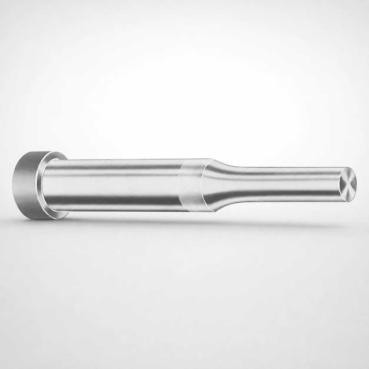
DAYTON Regular Punches - Metric, X Tip
Regular Punches - Metric, X Tip from DAYTON are designed for accurate punching in tight tool layouts where consistent penetration and stable guidance matter. The metric punch format supports efficient die applications and repeatable forming cycles.
- Built for close-space punching with a metric configuration
- Designed with the X tip shape to control point engagement
- Selected PS or M2 steel materials support wear resistance
- Typical use in progressive dies and precision forming operations
Specifications
318 configurations available
| Tip shape | Material | D (Shank dia.) (mm) | L1 (Point Length) (mm) | L (Length) (mm) | P Dimension (mm) | W Dimension (mm) | R Dimension (mm) |
|---|---|---|---|---|---|---|---|
| H | M2 | 04 | 8 ~ 13 | 40 ~ 100 | 1.3 ~ 3.95 | 1.3 ~ 1.59 | - |
| H | M2 | 04 | 8 ~ 13 | 40 ~ 100 | 1.3 ~ 3.95 | 1.6 ~ 3.95 | - |
| H | PS | 04 | 8 ~ 13 | 40 ~ 100 | 1.3 ~ 3.95 | 1.3 ~ 1.59 | - |
| H | PS | 04 | 8 ~ 13 | 40 ~ 100 | 1.3 ~ 3.95 | 1.6 ~ 3.95 | - |
| H | M2 | 05 | 13 ~ 19 | 40 ~ 100 | 1.6 ~ 4.95 | 1.6 ~ 4.95 | - |
| H | PS | 05 | 13 ~ 19 | 40 ~ 100 | 1.6 ~ 4.95 | 1.6 ~ 4.95 | - |
| H | M2 | 06 | 13 ~ 19 | 40 ~ 100 | 1.6 ~ 5.95 | 1.6 ~ 5.95 | - |
| H | PS | 06 | 13 ~ 19 | 40 ~ 100 | 1.6 ~ 5.95 | 1.6 ~ 5.95 | - |
| H | M2 | 08 | 19 ~ 25 | 50 ~ 100 | 2.5 ~ 7.95 | 2.5 ~ 7.95 | - |
| H | PS | 08 | 19 ~ 25 | 50 ~ 100 | 2.5 ~ 7.95 | 2.5 ~ 7.95 | - |
| H | M2 | 10 | 19 ~ 25 | 50 ~ 100 | 3.2 ~ 9.95 | 3.2 ~ 9.95 | - |
| H | PS | 10 | 19 ~ 25 | 50 ~ 100 | 3.2 ~ 9.95 | 3.2 ~ 9.95 | - |
| H | M2 | 13 | 19 ~ 25 | 50 ~ 100 | 4 ~ 12.95 | 4 ~ 4.49 | - |
| H | M2 | 13 | 19 ~ 25 | 50 ~ 100 | 4 ~ 12.95 | 4.5 ~ 12.95 | - |
| H | PS | 13 | 19 ~ 25 | 50 ~ 100 | 4 ~ 12.95 | 4 ~ 4.49 | - |
| H | PS | 13 | 19 ~ 25 | 50 ~ 100 | 4 ~ 12.95 | 4.5 ~ 12.95 | - |
| H | M2 | 16 | 19 ~ 25 | 50 ~ 100 | 6 ~ 15.95 | 6 ~ 15.95 | - |
| H | PS | 16 | 19 ~ 25 | 50 ~ 100 | 6 ~ 15.95 | 6 ~ 15.95 | - |
| H | M2 | 20 | 19 ~ 25 | 56 ~ 100 | 6 ~ 19.95 | 6 ~ 7.99 | - |
| H | M2 | 20 | 19 ~ 25 | 56 ~ 100 | 6 ~ 19.95 | 8 ~ 19.95 | - |
| H | PS | 20 | 19 ~ 25 | 56 ~ 100 | 6 ~ 19.95 | 6 ~ 7.99 | - |
| H | PS | 20 | 19 ~ 25 | 56 ~ 100 | 6 ~ 19.95 | 8 ~ 19.95 | - |
| H | M2 | 25 | 19 ~ 25 | 56 ~ 100 | 6 ~ 24.95 | 6 ~ 8.99 | - |
| H | M2 | 25 | 19 ~ 25 | 56 ~ 100 | 6 ~ 24.95 | 9 ~ 24.95 | - |
| H | PS | 25 | 19 ~ 25 | 56 ~ 100 | 6 ~ 24.95 | 6 ~ 8.99 | - |
| H | PS | 25 | 19 ~ 25 | 56 ~ 100 | 6 ~ 24.95 | 9 ~ 24.95 | - |
| H | M2 | 32 | 25 ~ 30 | 63 ~ 100 | 7.2 ~ 31.95 | 7.2 ~ 9.99 | - |
| H | M2 | 32 | 25 ~ 30 | 63 ~ 100 | 7.2 ~ 31.95 | 10 ~ 31.95 | - |
| H | PS | 32 | 25 ~ 30 | 63 ~ 100 | 7.2 ~ 31.95 | 7.2 ~ 9.99 | - |
| H | PS | 32 | 25 ~ 30 | 63 ~ 100 | 7.2 ~ 31.95 | 10 ~ 31.95 | - |
| J | M2 | 04 | 8 ~ 13 | 40 ~ 100 | 1.3 ~ 3.95 | 1.3 ~ 1.59 | - |
| J | M2 | 04 | 8 ~ 13 | 40 ~ 100 | 1.3 ~ 3.95 | 1.6 ~ 3.95 | - |
| J | PS | 04 | 8 ~ 13 | 40 ~ 100 | 1.3 ~ 3.95 | 1.3 ~ 1.59 | - |
| J | PS | 04 | 8 ~ 13 | 40 ~ 100 | 1.3 ~ 3.95 | 1.6 ~ 3.95 | - |
| J | M2 | 05 | 13 ~ 19 | 40 ~ 100 | 1.6 ~ 4.95 | 1.6 ~ 4.95 | - |
| J | PS | 05 | 13 ~ 19 | 40 ~ 100 | 1.6 ~ 4.95 | 1.6 ~ 4.95 | - |
| J | M2 | 06 | 13 ~ 19 | 40 ~ 100 | 1.6 ~ 5.95 | 1.6 ~ 5.95 | - |
| J | PS | 06 | 13 ~ 19 | 40 ~ 100 | 1.6 ~ 5.95 | 1.6 ~ 5.95 | - |
| J | M2 | 08 | 19 ~ 25 | 50 ~ 100 | 2.5 ~ 7.95 | 2.5 ~ 7.95 | - |
| J | PS | 08 | 19 ~ 25 | 50 ~ 100 | 2.5 ~ 7.95 | 2.5 ~ 7.95 | - |
| J | M2 | 10 | 19 ~ 25 | 50 ~ 100 | 3.2 ~ 9.95 | 3.2 ~ 9.95 | - |
| J | PS | 10 | 19 ~ 25 | 50 ~ 100 | 3.2 ~ 9.95 | 3.2 ~ 9.95 | - |
| J | M2 | 13 | 19 ~ 25 | 50 ~ 100 | 4 ~ 12.95 | 4 ~ 4.49 | - |
| J | M2 | 13 | 19 ~ 25 | 50 ~ 100 | 4 ~ 12.95 | 4.5 ~ 12.95 | - |
| J | PS | 13 | 19 ~ 25 | 50 ~ 100 | 4 ~ 12.95 | 4 ~ 4.49 | - |
| J | PS | 13 | 19 ~ 25 | 50 ~ 100 | 4 ~ 12.95 | 4.5 ~ 12.95 | - |
| J | M2 | 16 | 19 ~ 25 | 50 ~ 100 | 6 ~ 15.95 | 6 ~ 15.95 | - |
| J | PS | 16 | 19 ~ 25 | 50 ~ 100 | 6 ~ 15.95 | 6 ~ 15.95 | - |
| J | M2 | 20 | 19 ~ 25 | 56 ~ 100 | 6 ~ 19.95 | 6 ~ 7.99 | - |
| J | M2 | 20 | 19 ~ 25 | 56 ~ 100 | 6 ~ 19.95 | 8 ~ 19.95 | - |
Product Guide
Application Scenarios+
These metric regular punches with an X tip option are used in injection-mold tooling when the punch action is part of post-forming, in-mold insertion, or precision blanking operations inside a multi-station tool layout. The controlled point engagement helps stabilize penetration where several features must share limited space.
- Progressive die tooling for formed features: The X tip supports repeatable forming cycles and consistent breakthrough, which is valuable for producing precise openings that later feed into assembly.
- Close-space connector or bracket components: When cavity or core geometry constrains approach, the X tip geometry and metric shank sizing (D 4–32 mm) enable accurate alignment and guidance.
- Precision housings with defined windows: Point length selections (L1 ranges from 8–30 mm) help match required penetration depth without overtravel, improving part definition and reducing edge variation.
Material & Process Details+
DAYTON regular punches are available in M2 or PS tool steel options, both selected for reliable wear performance during repeated punching/blanking cycles. M2 is a high-speed steel commonly chosen when wear resistance and edge stability under load are critical.
- M2 option: Typically used where higher hardness and sustained cutting performance are needed; the trade-off is that toughness margins may require careful setup and guidance.
- PS option: A punch steel alternative prioritized for consistent forming behavior and durability in general punching applications.
- Manufacturing: Punch bodies are precision-machined to the specified shank diameter D (4–32 mm), then heat treated to the appropriate hardened state for the selected grade to balance hardness, wear resistance, and dimensional stability.
Tip geometry (including the X tip) is ground/finished to maintain controlled point engagement, directly affecting wear behavior at the cutting edge.
Sizing & Selection Guide+
Selection starts by matching the punch shank and point geometry to the die set and required penetration. Use the shank diameter D = 4–32 mm to match the guide and clearance design in your holder or bushing, ensuring proper alignment under load.
- Choose point length (L1): Select L1 from 8–13, 13–19, 19–25, or 25–30 mm to achieve the needed penetration depth while avoiding excessive point overtravel.
- Select overall punch length (L): L is available in ranges such as 40–100, 50–100, 56–100, or 63–100 mm depending on tooling stack height and stroke limits.
- Set engagement features: Use P (0.8–10 mm), W (1.3–10 mm), and R (0.2 mm) to align with your die opening geometry and edge formation requirements.
Confirm clearance/fit with your guide bush: tighter fits improve guidance but can increase heat buildup; use your tool’s design tolerances to finalize the working diameters and ensure consistent feeding in progressive stations.
Frequently Asked Questions
How should I select the right X-tip geometry for close-space punching in a progressive station?+
What shank diameter range (D) is available, and how does it affect guide/bushing selection?+
Between M2 and PS steel, which one is better suited for edge wear in repeated cycles?+
How do I determine the correct point length (L1) for the required penetration depth?+
Which dimensions (P, W, R) must match the die opening for consistent part definition?+
Related Products






Need Custom Specifications?
Our engineering team can help with custom configurations, material selection, and volume pricing.