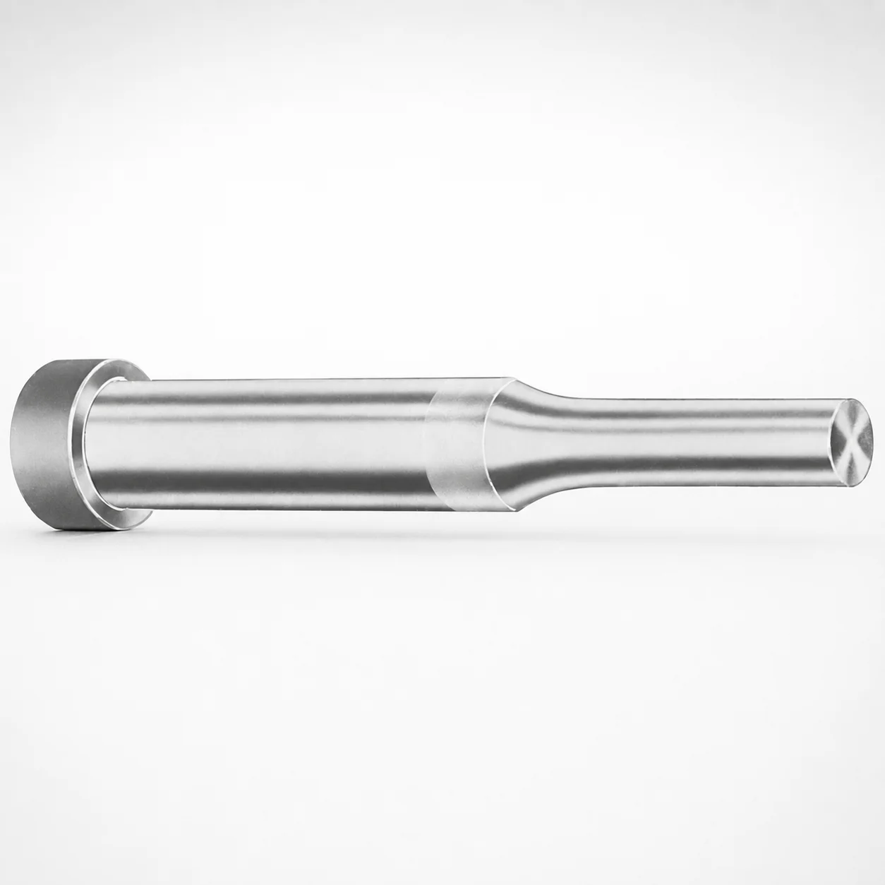
Regular Punches Metric X-Tip
Regular Punches Metric (X-tip) are precision punch components designed for consistent part ejection and accurate locating in metal forming applications. The X-tip geometry helps improve centering stability under repeated press cycles.
- X-tip punch point geometry for stable positioning during punching operations
- Options include M2 Steel or PS Steel for fit to wear demands
- Controlled point and shank dimensions support repeatable assembly in toolsets
- Dayton metric punch design for standard die and mold punch tooling
Specifications
477 configurations available
| Tip shape | Material | D (Shank dia.) (mm) | L1 (Point Length) (mm) | L (Length) (mm) | P Dimension (mm) | W Dimension (mm) | R Dimension (mm) |
|---|---|---|---|---|---|---|---|
| H | M2 | 04 | 8 ~ 13 | 40 ~ 100 | 1.3 ~ 3.95 | 1.3 ~ 1.59 | - |
| H | M2 | 04 | 8 ~ 13 | 40 ~ 100 | 1.3 ~ 3.95 | 1.6 ~ 3.95 | - |
| H | A2 | 04 | 8 ~ 13 | 40 ~ 100 | 1.3 ~ 3.95 | 1.3 ~ 1.59 | - |
| H | A2 | 04 | 8 ~ 13 | 40 ~ 100 | 1.3 ~ 3.95 | 1.6 ~ 3.95 | - |
| H | PS | 04 | 8 ~ 13 | 40 ~ 100 | 1.3 ~ 3.95 | 1.3 ~ 1.59 | - |
| H | PS | 04 | 8 ~ 13 | 40 ~ 100 | 1.3 ~ 3.95 | 1.6 ~ 3.95 | - |
| H | M2 | 05 | 13 ~ 19 | 40 ~ 100 | 1.6 ~ 4.95 | 1.6 ~ 4.95 | - |
| H | A2 | 05 | 13 ~ 19 | 40 ~ 100 | 1.6 ~ 4.95 | 1.6 ~ 4.95 | - |
| H | PS | 05 | 13 ~ 19 | 40 ~ 100 | 1.6 ~ 4.95 | 1.6 ~ 4.95 | - |
| H | M2 | 06 | 13 ~ 19 | 40 ~ 100 | 1.6 ~ 5.95 | 1.6 ~ 5.95 | - |
| H | A2 | 06 | 13 ~ 19 | 40 ~ 100 | 1.6 ~ 5.95 | 1.6 ~ 5.95 | - |
| H | PS | 06 | 13 ~ 19 | 40 ~ 100 | 1.6 ~ 5.95 | 1.6 ~ 5.95 | - |
| H | M2 | 08 | 19 ~ 25 | 50 ~ 100 | 2.5 ~ 7.95 | 2.5 ~ 7.95 | - |
| H | A2 | 08 | 19 ~ 25 | 50 ~ 100 | 2.5 ~ 7.95 | 2.5 ~ 7.95 | - |
| H | PS | 08 | 19 ~ 25 | 50 ~ 100 | 2.5 ~ 7.95 | 2.5 ~ 7.95 | - |
| H | M2 | 10 | 19 ~ 25 | 50 ~ 100 | 3.2 ~ 9.95 | 3.2 ~ 9.95 | - |
| H | A2 | 10 | 19 ~ 25 | 50 ~ 100 | 3.2 ~ 9.95 | 3.2 ~ 9.95 | - |
| H | PS | 10 | 19 ~ 25 | 50 ~ 100 | 3.2 ~ 9.95 | 3.2 ~ 9.95 | - |
| H | M2 | 13 | 19 ~ 25 | 50 ~ 100 | 4 ~ 12.95 | 4 ~ 4.49 | - |
| H | M2 | 13 | 19 ~ 25 | 50 ~ 100 | 4 ~ 12.95 | 4.5 ~ 12.95 | - |
| H | A2 | 13 | 19 ~ 25 | 50 ~ 100 | 4 ~ 12.95 | 4 ~ 4.49 | - |
| H | A2 | 13 | 19 ~ 25 | 50 ~ 100 | 4 ~ 12.95 | 4.5 ~ 12.95 | - |
| H | PS | 13 | 19 ~ 25 | 50 ~ 100 | 4 ~ 12.95 | 4 ~ 4.49 | - |
| H | PS | 13 | 19 ~ 25 | 50 ~ 100 | 4 ~ 12.95 | 4.5 ~ 12.95 | - |
| H | M2 | 16 | 19 ~ 25 | 50 ~ 100 | 6 ~ 15.95 | 6 ~ 15.95 | - |
| H | A2 | 16 | 19 ~ 25 | 50 ~ 100 | 6 ~ 15.95 | 6 ~ 15.95 | - |
| H | PS | 16 | 19 ~ 25 | 50 ~ 100 | 6 ~ 15.95 | 6 ~ 15.95 | - |
| H | M2 | 20 | 19 ~ 25 | 56 ~ 100 | 6 ~ 19.95 | 6 ~ 7.99 | - |
| H | M2 | 20 | 19 ~ 25 | 56 ~ 100 | 6 ~ 19.95 | 8 ~ 19.95 | - |
| H | A2 | 20 | 19 ~ 25 | 56 ~ 100 | 6 ~ 19.95 | 6 ~ 7.99 | - |
| H | A2 | 20 | 19 ~ 25 | 56 ~ 100 | 6 ~ 19.95 | 8 ~ 19.95 | - |
| H | PS | 20 | 19 ~ 25 | 56 ~ 100 | 6 ~ 19.95 | 6 ~ 7.99 | - |
| H | PS | 20 | 19 ~ 25 | 56 ~ 100 | 6 ~ 19.95 | 8 ~ 19.95 | - |
| H | M2 | 25 | 19 ~ 25 | 56 ~ 100 | 6 ~ 24.95 | 6 ~ 8.99 | - |
| H | M2 | 25 | 19 ~ 25 | 56 ~ 100 | 6 ~ 24.95 | 9 ~ 24.95 | - |
| H | A2 | 25 | 19 ~ 25 | 56 ~ 100 | 6 ~ 24.95 | 6 ~ 8.99 | - |
| H | A2 | 25 | 19 ~ 25 | 56 ~ 100 | 6 ~ 24.95 | 9 ~ 24.95 | - |
| H | PS | 25 | 19 ~ 25 | 56 ~ 100 | 6 ~ 24.95 | 6 ~ 8.99 | - |
| H | PS | 25 | 19 ~ 25 | 56 ~ 100 | 6 ~ 24.95 | 9 ~ 24.95 | - |
| H | M2 | 32 | 25 ~ 30 | 63 ~ 100 | 7.2 ~ 31.95 | 7.2 ~ 9.99 | - |
| H | M2 | 32 | 25 ~ 30 | 63 ~ 100 | 7.2 ~ 31.95 | 10 ~ 31.95 | - |
| H | A2 | 32 | 25 ~ 30 | 63 ~ 100 | 7.2 ~ 31.95 | 7.2 ~ 9.99 | - |
| H | A2 | 32 | 25 ~ 30 | 63 ~ 100 | 7.2 ~ 31.95 | 10 ~ 31.95 | - |
| H | PS | 32 | 25 ~ 30 | 63 ~ 100 | 7.2 ~ 31.95 | 7.2 ~ 9.99 | - |
| H | PS | 32 | 25 ~ 30 | 63 ~ 100 | 7.2 ~ 31.95 | 10 ~ 31.95 | - |
| J | M2 | 04 | 8 ~ 13 | 40 ~ 100 | 1.3 ~ 3.95 | 1.3 ~ 1.59 | - |
| J | M2 | 04 | 8 ~ 13 | 40 ~ 100 | 1.3 ~ 3.95 | 1.6 ~ 3.95 | - |
| J | A2 | 04 | 8 ~ 13 | 40 ~ 100 | 1.3 ~ 3.95 | 1.3 ~ 1.59 | - |
| J | A2 | 04 | 8 ~ 13 | 40 ~ 100 | 1.3 ~ 3.95 | 1.6 ~ 3.95 | - |
| J | PS | 04 | 8 ~ 13 | 40 ~ 100 | 1.3 ~ 3.95 | 1.3 ~ 1.59 | - |
Product Guide
Application Scenarios+
Regular punches with an X-tip are used in injection mold tooling and metal forming setups where repeatable locating, part ejection, and stable punch centering are critical. In automotive connector and bracket tooling, the X-tip point helps maintain coaxiality across repeated press strokes, supporting consistent cavity pick-up and reducing drift-related defects.
- Die and mold insert applications: Suitable for standard punch stations where controlled shank fit and point geometry support repeatable assembly.
- High-cycle metal forming: The X-tip promotes stable positioning under repetitive loading, improving reliability when stripping and forming cycles are frequent.
- Multi-cavity tooling: Works well when multiple identical punches must maintain alignment tolerances across toolsets.
This variant is specifically suited because the X-tip geometry is designed for centering stability, while the offered material options (M2, A2, PS) allow selection based on wear versus toughness requirements.
Material & Process Details+
This punch series is offered in M2, A2, and PS tool steel options, allowing engineers to balance wear resistance and toughness based on application severity. M2 and A2 are high-speed steel grades commonly selected for improved wear performance at elevated temperatures, while PS is typically chosen when tooling priorities emphasize hardness for consistent punching and economical durability.
- M2 steel: Strong wear resistance for longer life under repeated punching; best when sliding/abrasive wear is a dominant concern.
- A2 steel: General-purpose tooling performance with robust hardness and good toughness for many die operations.
- PS steel: Often selected for wear-focused service; trade-off can be reduced toughness compared with tougher grades.
Heat treatment states are supplied as ready-to-use punch components in hardened condition per manufacturer process; exact HRC values are not provided in the input data. Final hardness and wear behavior depend on the selected steel grade, point geometry, and operating load.
Sizing & Selection Guide+
To select the correct regular punch dimensions, start with the required shank diameter D and match it to the tooling pocket and guide system. This series supports D = 4 ~ 32 mm, so choose the smallest diameter that maintains rigidity for your punch length and load.
- Match point/stroke requirements: Select L1 (point length) from 8–13, 13–19, 19–25, or 25–30 mm based on required engagement depth in the die.
- Overall length L: Choose from 40–100, 50–100, 56–100, or 63–100 mm to ensure correct projection and safe clearance during cycles.
- Geometry parameters: Confirm P = 0.8 ~ 10 mm, W = 1.3 ~ 10 mm, and the specified R = 0.2 mm to align with your tool’s locating and stripping interface.
Where possible, maintain a controlled fit between the D shank and the guide bore/holder. The input does not provide explicit tolerances, so use the manufacturer’s standard tolerance class for assembly verification and avoid overconstraint that could cause binding under thermal growth.
Frequently Asked Questions
Which tip shapes (H, J, K, L, N, O, R, V, X, Y, Z) are compatible with the X-tip centering function in this punch series?+
This series specifies a variable tip shape option set: H, J, K, L, N, O, R, V, X, Y, Z. The “X-tip” variant indicates the X-tip geometry selection for centering stability, while other letters correspond to alternate point geometries. To keep centering behavior consistent, select the X tip shape in your configuration rather than a different tip code.
How do I choose point length (L1) versus overall length (L) so the punch engages correctly without bottoming?+
Select L1 (8–13, 13–19, 19–25, or 25–30 mm) to match the required engagement depth into the die/stripper interface. Then choose L (40–100, 50–100, 56–100, or 63–100 mm) so the punch projection provides clearance during the full cycle. Verify the stack-up in your tool (holder height, wear inserts, and stripper travel) before finalizing the combination.
What shank diameter (D) range is available, and how does it affect guide fit in the punch holder?+
Available D (shank diameter) is 4 ~ 32 mm. A larger D increases rigidity and resistance to bending, but it also requires a corresponding guide bore and holder size. Use the same D for the holder/guide system to maintain the intended fit; the input does not list tolerances, so confirm fit class using the supplier’s standard tolerance documentation.
When should I select M2 or A2 instead of PS for die and mold punching wear performance?+
The series offers M2, A2, and PS materials, enabling selection by wear versus toughness needs. Choose M2 when wear resistance under repetitive punching is the primary driver. Select A2 for broader tooling performance where a balance of hardness and toughness is required. Consider PS for wear-focused service where performance targets and durability expectations align with the application load profile.
Which geometry parameters (P, W, R) must match the die interface for stable positioning?+
This series specifies P = 0.8 ~ 10 mm, W = 1.3 ~ 10 mm, and R = 0.2 mm. These dimensions influence how the punch point interfaces with your locating and stripping surfaces. For stable positioning, ensure your die/core cavity features and any mating countersinks/reliefs are designed for the same P, W, and the specified point radius R.
Related Products






Need Custom Specifications?
Our engineering team can help with custom configurations, material selection, and volume pricing.