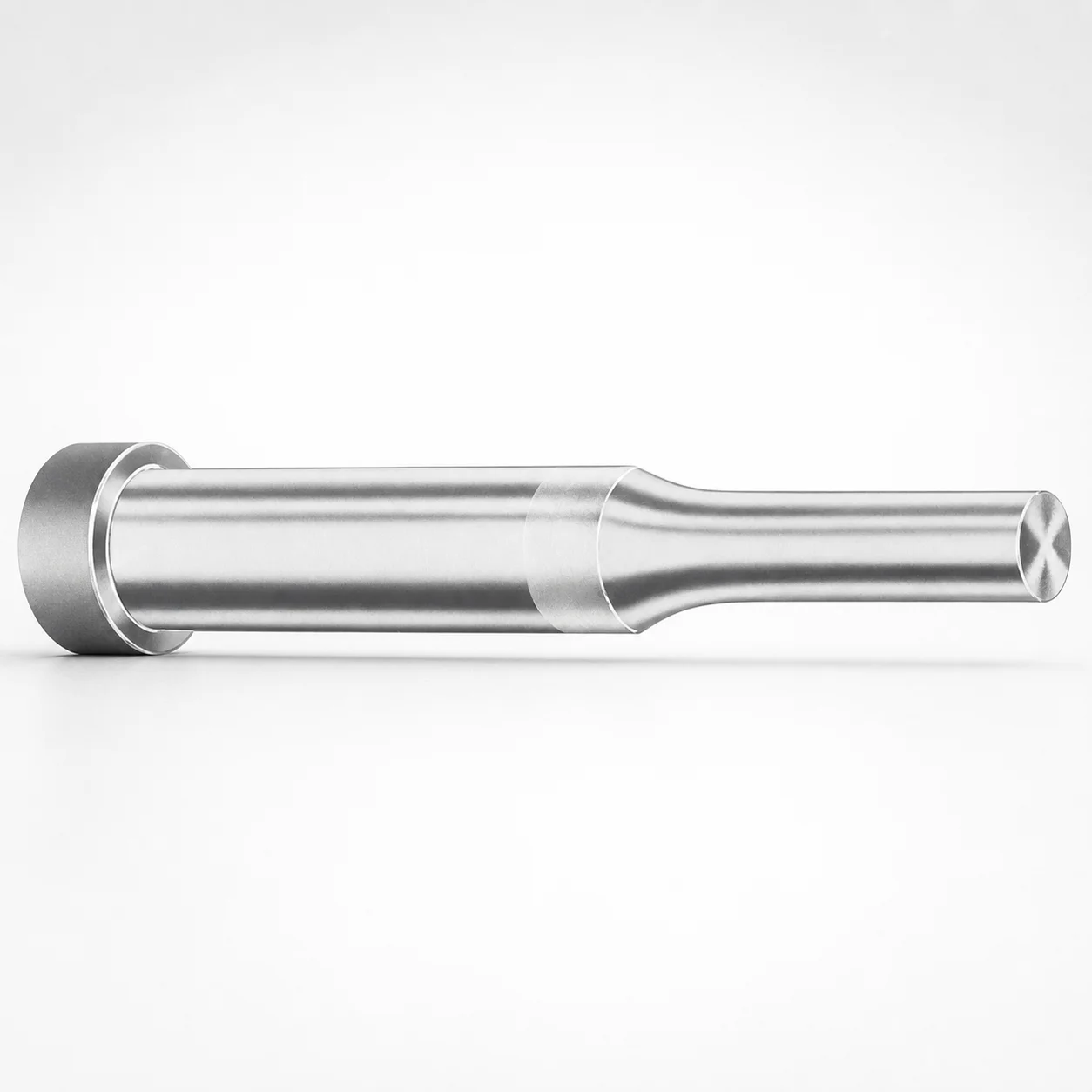
DAYTON XNT DayTiN Coating Regular Punches - Metric X-Tip
Regular Punches - Metric (DAYTON XNT DayTiN® Coating) with an X-tip are designed for stable punching in progressive and transfer dies. The coating helps reduce wear while maintaining consistent cutting performance.
- X-tip geometry supports controlled material forming and reliable punch engagement
- DAYTON XNT DayTiN® coating improves surface durability for long production runs
- Hardened punch steel options help resist abrasive wear in repeat operations
- Metric regular punch style suitable for die maintenance kits and tooling refresh
Specifications
319 configurations available
| Tip shape | Material | D (Shank dia.) (mm) | L1 (Point Length) (mm) | L (Length) (mm) | P Dimension (mm) | W Dimension (mm) | R Dimension (mm) |
|---|---|---|---|---|---|---|---|
| H | M2 | 04 | 8 ~ 13 | 40 ~ 100 | 1.3 ~ 3.95 | 1.3 ~ 1.59 | - |
| H | M2 | 04 | 8 ~ 13 | 40 ~ 100 | 1.3 ~ 3.95 | 1.6 ~ 3.95 | - |
| H | PS | 04 | 8 ~ 13 | 40 ~ 100 | 1.3 ~ 3.95 | 1.3 ~ 1.59 | - |
| H | PS | 04 | 8 ~ 13 | 40 ~ 100 | 1.3 ~ 3.95 | 1.6 ~ 3.95 | - |
| H | M2 | 05 | 13 ~ 19 | 40 ~ 100 | 1.6 ~ 4.95 | 1.6 ~ 4.95 | - |
| H | PS | 05 | 13 ~ 19 | 40 ~ 100 | 1.6 ~ 4.95 | 1.6 ~ 4.95 | - |
| H | M2 | 06 | 13 ~ 19 | 40 ~ 100 | 1.6 ~ 5.95 | 1.6 ~ 5.95 | - |
| H | PS | 06 | 13 ~ 19 | 40 ~ 100 | 1.6 ~ 5.95 | 1.6 ~ 5.95 | - |
| H | M2 | 08 | 19 ~ 25 | 50 ~ 100 | 2.5 ~ 7.95 | 2.5 ~ 7.95 | - |
| H | PS | 08 | 19 ~ 25 | 50 ~ 100 | 2.5 ~ 7.95 | 2.5 ~ 7.95 | - |
| H | M2 | 10 | 19 ~ 25 | 50 ~ 100 | 3.2 ~ 9.95 | 3.2 ~ 9.95 | - |
| H | PS | 10 | 19 ~ 25 | 50 ~ 100 | 3.2 ~ 9.95 | 3.2 ~ 9.95 | - |
| H | M2 | 13 | 19 ~ 25 | 50 ~ 100 | 4 ~ 12.95 | 4 ~ 4.49 | - |
| H | M2 | 13 | 19 ~ 25 | 50 ~ 100 | 4 ~ 12.95 | 4.5 ~ 12.95 | - |
| H | PS | 13 | 19 ~ 25 | 50 ~ 100 | 4 ~ 12.95 | 4 ~ 4.49 | - |
| H | PS | 13 | 19 ~ 25 | 50 ~ 100 | 4 ~ 12.95 | 4.5 ~ 12.95 | - |
| H | M2 | 16 | 19 ~ 25 | 50 ~ 100 | 6 ~ 15.95 | 6 ~ 15.95 | - |
| H | PS | 16 | 19 ~ 25 | 50 ~ 100 | 6 ~ 15.95 | 6 ~ 15.95 | - |
| H | M2 | 20 | 19 ~ 25 | 56 ~ 100 | 6 ~ 19.95 | 6 ~ 7.99 | - |
| H | M2 | 20 | 19 ~ 25 | 56 ~ 100 | 6 ~ 19.95 | 8 ~ 19.95 | - |
| H | PS | 20 | 19 ~ 25 | 56 ~ 100 | 6 ~ 19.95 | 6 ~ 7.99 | - |
| H | PS | 20 | 19 ~ 25 | 56 ~ 100 | 6 ~ 19.95 | 8 ~ 19.95 | - |
| H | M2 | 25 | 19 ~ 25 | 56 ~ 100 | 6 ~ 24.95 | 6 ~ 8.99 | - |
| H | M2 | 25 | 19 ~ 25 | 56 ~ 100 | 6 ~ 24.95 | 9 ~ 24.95 | - |
| H | PS | 25 | 19 ~ 25 | 56 ~ 100 | 6 ~ 24.95 | 6 ~ 8.99 | - |
| H | PS | 25 | 19 ~ 25 | 56 ~ 100 | 6 ~ 24.95 | 9 ~ 24.95 | - |
| H | M2 | 32 | 25 ~ 30 | 63 ~ 100 | 7.2 ~ 31.95 | 7.2 ~ 9.99 | - |
| H | M2 | 32 | 25 ~ 30 | 63 ~ 100 | 7.2 ~ 31.95 | 10 ~ 31.95 | - |
| H | PS | 32 | 25 ~ 30 | 63 ~ 100 | 7.2 ~ 31.95 | 7.2 ~ 9.99 | - |
| H | PS | 32 | 25 ~ 30 | 63 ~ 100 | 7.2 ~ 31.95 | 10 ~ 31.95 | - |
| J | M2 | 04 | 8 ~ 13 | 40 ~ 100 | 1.3 ~ 3.95 | 1.3 ~ 1.59 | - |
| J | M2 | 04 | 8 ~ 13 | 40 ~ 100 | 1.3 ~ 3.95 | 1.6 ~ 3.95 | - |
| J | PS | 04 | 8 ~ 13 | 40 ~ 100 | 1.3 ~ 3.95 | 1.3 ~ 1.59 | - |
| J | PS | 04 | 8 ~ 13 | 40 ~ 100 | 1.3 ~ 3.95 | 1.6 ~ 3.95 | - |
| J | M2 | 05 | 13 ~ 19 | 40 ~ 100 | 1.6 ~ 4.95 | 1.6 ~ 4.95 | - |
| J | PS | 05 | 13 ~ 19 | 40 ~ 100 | 1.6 ~ 4.95 | 1.6 ~ 4.95 | - |
| J | M2 | 06 | 13 ~ 19 | 40 ~ 100 | 1.6 ~ 5.95 | 1.6 ~ 5.95 | - |
| J | PS | 06 | 13 ~ 19 | 40 ~ 100 | 1.6 ~ 5.95 | 1.6 ~ 5.95 | - |
| J | M2 | 08 | 19 ~ 25 | 50 ~ 100 | 2.5 ~ 7.95 | 2.5 ~ 7.95 | - |
| J | PS | 08 | 19 ~ 25 | 50 ~ 100 | 2.5 ~ 7.95 | 2.5 ~ 7.95 | - |
| J | M2 | 10 | 19 ~ 25 | 50 ~ 100 | 3.2 ~ 9.95 | 3.2 ~ 9.95 | - |
| J | PS | 10 | 19 ~ 25 | 50 ~ 100 | 3.2 ~ 9.95 | 3.2 ~ 9.95 | - |
| J | M2 | 13 | 19 ~ 25 | 50 ~ 100 | 4 ~ 12.95 | 4 ~ 4.49 | - |
| J | M2 | 13 | 19 ~ 25 | 50 ~ 100 | 4 ~ 12.95 | 4.5 ~ 12.95 | - |
| J | PS | 13 | 19 ~ 25 | 50 ~ 100 | 4 ~ 12.95 | 4 ~ 4.49 | - |
| J | PS | 13 | 19 ~ 25 | 50 ~ 100 | 4 ~ 12.95 | 4.5 ~ 12.95 | - |
| J | M2 | 16 | 19 ~ 25 | 50 ~ 100 | 6 ~ 15.95 | 6 ~ 15.95 | - |
| J | PS | 16 | 19 ~ 25 | 50 ~ 100 | 6 ~ 15.95 | 6 ~ 15.95 | - |
| J | M2 | 20 | 19 ~ 25 | 56 ~ 100 | 6 ~ 19.95 | 6 ~ 7.99 | - |
| J | M2 | 20 | 19 ~ 25 | 56 ~ 100 | 6 ~ 19.95 | 8 ~ 19.95 | - |
Product Guide
Application Scenarios+
These metric regular punches with an X-tip are commonly used in progressive and transfer injection mold tooling where consistent blanking and feed-to-feed repeatability are critical. The DayTiN® XNT coating and hardened punch body support stable cutting across long production runs, helping reduce surface wear on the working end.
- Automotive and appliance components: In dies that stamp/blank thin electrical, trim, or connector features, the X-tip geometry improves controlled material forming and reliable punch engagement, reducing the risk of edge chipping during high-cycle operation.
- Electronics housings and brackets: For repeated openings and precision cutouts, the DayTiN® coating improves durability and helps maintain consistent blanking performance as abrasive debris accumulates in die cavities.
- Tooling refresh kits: When replacing standard punches in existing maintenance programs, the metric shank diameter range (D 4–32 mm) and multiple point lengths (L1 8–30 mm) allow straightforward dimensional matching to legacy die layouts.
Material & Process Details+
This punch series is offered in M2 or PS materials, paired with a DAYTON XNT DayTiN® coating for improved wear resistance at the cutting interface. M2 tool steel is commonly used for cutting tools because it balances high hardness and wear resistance with adequate toughness for intermittent and continuous die work; PS is typically selected where robust performance and good wear behavior are required with a different toughness-to-wear balance.
- Coating effect: The XNT DayTiN® layer increases surface hardness and reduces friction/wear at the working tip, supporting longer die life.
- Heat treatment state: The punch body is supplied as a hardened punch for durable die performance in repeat operations.
- Trade-offs: Higher wear resistance at the tip can reduce tolerance to edge impacts; pairing the correct tip shape (H/J/K…/X/Y/Z) with the intended material feed helps manage toughness versus abrasion resistance.
Sizing & Selection Guide+
Select dimensions by matching the punch working geometry to the corresponding die opening and stripper/guide constraints in your mold tool. Start with D (shank diameter) = 4–32 mm to confirm fit in the punch guide and bushing. Then choose the correct point length L1 from the available ranges (8–13, 13–19, 19–25, or 25–30 mm) based on the required penetration depth into the workpiece within the die height.
- Overall length L: Verify that the selected L = 40–100, 50–100, 56–100, or 63–100 mm maintains proper stick-out and clearance to the bolster/holder during cycling.
- Cutting geometry: Use the specified tip shape (including X-tip) and tune the punch face dimensions using P = 0.8–10 mm and W = 1.3–10 mm to align with die land and clearance design.
- Radius R: Set R = 0.2 mm as given to maintain consistent edge rounding and reduce stress concentration.
Where you reuse existing die blocks, prioritize matching D, L, and L1 first; then confirm P/W compatibility with the die opening profile and your press/blanking gap settings.
Frequently Asked Questions
Which tip shape options are available for this metric regular punch series, and how does the X-tip impact blanking control?+
How do I choose the correct shank diameter (D) and overall length (L) to fit the punch guide and holder?+
What point length (L1) should I select for proper penetration depth, and what are the available L1 ranges?+
How do the available materials (M2 vs PS) and the DayTiN XNT coating affect wear performance in high-cycle punching?+
How do I match the P and W dimensions (and the fixed R) to my die opening geometry?+
Related Products






Need Custom Specifications?
Our engineering team can help with custom configurations, material selection, and volume pricing.