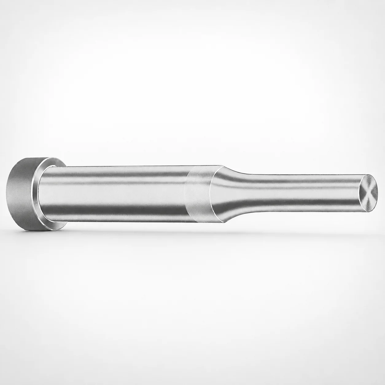
Inch Standard Regular Punches XNT DayTiN® Coating
Regular Punches (XNT DayTiN® Coating) are designed for inch die sets where stable punch performance and reliable wear resistance matter. The DayTiN® surface treatment helps protect cutting edges during repetitive forming and punching operations.
- Coated punch surface improves resistance to wear during production cycles
- XNT DayTiN® coating supports consistent dimensional stability in use
- Manufactured for repeatable assembly fit in inch-standard tooling
- Commonly used in forming, blanking, and punching stages for precision dies
Specifications
882 configurations available
| Tip shape | D (Shank dia.) (in) | Standard [S] Point Length B & L (Length) (coded inch) | Alternate [B] Point Length B & L (Length) (coded inch) | Alternate [C] Point Length B & L (Length) (coded inch) | Alternate [D] Point Length B & L (Length) (coded inch) | Alternate [E] Point Length B & L (Length) (coded inch) | P Dimension (in) | W Dimension (in) | R Dimension (in) |
|---|---|---|---|---|---|---|---|---|---|
| H | 12(0.1250") | - | 150 ~ 400 | - | - | - | 0.062 ~ 0.125 | 0.062 ~ 0.125 | - |
| H | 12(0.1250") | 150 ~ 400 | - | - | - | - | 0.062 ~ 0.125 | 0.062 ~ 0.125 | - |
| H | 18(0.1875") | - | 150 ~ 500 | - | - | - | 0.062 ~ 0.1875 | 0.062 ~ 0.1875 | - |
| H | 18(0.1875") | 150 ~ 500 | - | - | - | - | 0.062 ~ 0.1875 | 0.062 ~ 0.1875 | - |
| H | 25(0.2500") | - | 150 ~ 600 | - | - | - | 0.062 ~ 0.25 | 0.062 ~ 0.0929 | - |
| H | 25(0.2500") | - | 150 ~ 600 | - | - | - | 0.062 ~ 0.25 | 0.093 ~ 0.25 | - |
| H | 25(0.2500") | 150 ~ 600 | - | - | - | - | 0.062 ~ 0.25 | 0.062 ~ 0.0929 | - |
| H | 25(0.2500") | 150 ~ 600 | - | - | - | - | 0.062 ~ 0.25 | 0.093 ~ 0.25 | - |
| H | 31(0.3125") | - | 150 ~ 600 | - | - | - | 0.062 ~ 0.3125 | 0.062 ~ 0.1249 | - |
| H | 31(0.3125") | - | 150 ~ 600 | - | - | - | 0.062 ~ 0.3125 | 0.125 ~ 0.3125 | - |
| H | 31(0.3125") | - | - | 175 ~ 600 | - | - | 0.062 ~ 0.3125 | 0.062 ~ 0.1249 | - |
| H | 31(0.3125") | - | - | 175 ~ 600 | - | - | 0.062 ~ 0.3125 | 0.125 ~ 0.3125 | - |
| H | 31(0.3125") | 150 ~ 600 | - | - | - | - | 0.062 ~ 0.3125 | 0.062 ~ 0.1249 | - |
| H | 31(0.3125") | 150 ~ 600 | - | - | - | - | 0.062 ~ 0.3125 | 0.125 ~ 0.3125 | - |
| H | 37(0.3750") | - | 175 ~ 600 | - | - | - | 0.08 ~ 0.375 | 0.08 ~ 0.1869 | - |
| H | 37(0.3750") | - | 175 ~ 600 | - | - | - | 0.08 ~ 0.375 | 0.187 ~ 0.375 | - |
| H | 37(0.3750") | - | - | 175 ~ 600 | - | - | 0.08 ~ 0.375 | 0.08 ~ 0.1869 | - |
| H | 37(0.3750") | - | - | 175 ~ 600 | - | - | 0.08 ~ 0.375 | 0.187 ~ 0.375 | - |
| H | 37(0.3750") | - | - | - | 200 ~ 600 | - | 0.08 ~ 0.375 | 0.08 ~ 0.1869 | - |
| H | 37(0.3750") | - | - | - | 200 ~ 600 | - | 0.08 ~ 0.375 | 0.187 ~ 0.375 | - |
| H | 37(0.3750") | 175 ~ 600 | - | - | - | - | 0.08 ~ 0.375 | 0.08 ~ 0.1869 | - |
| H | 37(0.3750") | 175 ~ 600 | - | - | - | - | 0.08 ~ 0.375 | 0.187 ~ 0.375 | - |
| H | 43(0.4375") | - | - | 200 ~ 700 | - | - | 0.158 ~ 0.4374 | 0.158 ~ 0.1869 | - |
| H | 43(0.4375") | - | - | 200 ~ 700 | - | - | 0.158 ~ 0.4374 | 0.187 ~ 0.4374 | - |
| H | 43(0.4375") | - | - | - | 200 ~ 700 | - | 0.158 ~ 0.4374 | 0.158 ~ 0.1869 | - |
| H | 43(0.4375") | - | - | - | 200 ~ 700 | - | 0.158 ~ 0.4374 | 0.187 ~ 0.4374 | - |
| H | 43(0.4375") | 200 ~ 700 | - | - | - | - | 0.158 ~ 0.4374 | 0.158 ~ 0.1869 | - |
| H | 43(0.4375") | 200 ~ 700 | - | - | - | - | 0.158 ~ 0.4374 | 0.187 ~ 0.4374 | - |
| H | 50(0.5000") | - | - | 200 ~ 700 | - | - | 0.158 ~ 0.5 | 0.158 ~ 0.1869 | - |
| H | 50(0.5000") | - | - | 200 ~ 700 | - | - | 0.158 ~ 0.5 | 0.187 ~ 0.5 | - |
| H | 50(0.5000") | - | - | - | 200 ~ 700 | - | 0.158 ~ 0.5 | 0.158 ~ 0.1869 | - |
| H | 50(0.5000") | - | - | - | 200 ~ 700 | - | 0.158 ~ 0.5 | 0.187 ~ 0.5 | - |
| H | 50(0.5000") | 200 ~ 700 | - | - | - | - | 0.158 ~ 0.5 | 0.158 ~ 0.1869 | - |
| H | 50(0.5000") | 200 ~ 700 | - | - | - | - | 0.158 ~ 0.5 | 0.187 ~ 0.5 | - |
| H | 62(0.6250") | - | - | - | 225 ~ 700 | - | 0.235 ~ 0.625 | 0.25 ~ 0.625 | - |
| H | 62(0.6250") | - | - | - | 225 ~ 700 | - | 0.235 ~ 0.625 | 0.235 ~ 0.2499 | - |
| H | 62(0.6250") | - | - | - | - | 225 ~ 700 | 0.235 ~ 0.625 | 0.25 ~ 0.625 | - |
| H | 62(0.6250") | - | - | - | - | 225 ~ 700 | 0.235 ~ 0.625 | 0.235 ~ 0.2499 | - |
| H | 62(0.6250") | 225 ~ 700 | - | - | - | - | 0.235 ~ 0.625 | 0.25 ~ 0.625 | - |
| H | 62(0.6250") | 225 ~ 700 | - | - | - | - | 0.235 ~ 0.625 | 0.235 ~ 0.2499 | - |
| H | 75(0.7500") | - | - | - | 225 ~ 700 | - | 0.235 ~ 0.75 | 0.235 ~ 0.3119 | - |
| H | 75(0.7500") | - | - | - | 225 ~ 700 | - | 0.235 ~ 0.75 | 0.312 ~ 0.75 | - |
| H | 75(0.7500") | - | - | - | - | 225 ~ 700 | 0.235 ~ 0.75 | 0.235 ~ 0.3119 | - |
| H | 75(0.7500") | - | - | - | - | 225 ~ 700 | 0.235 ~ 0.75 | 0.312 ~ 0.75 | - |
| H | 75(0.7500") | 225 ~ 700 | - | - | - | - | 0.235 ~ 0.75 | 0.235 ~ 0.3119 | - |
| H | 75(0.7500") | 225 ~ 700 | - | - | - | - | 0.235 ~ 0.75 | 0.312 ~ 0.75 | - |
| H | 87(0.8750") | - | - | - | 225 ~ 700 | - | 0.235 ~ 0.875 | 0.235 ~ 0.3119 | - |
| H | 87(0.8750") | - | - | - | 225 ~ 700 | - | 0.235 ~ 0.875 | 0.312 ~ 0.875 | - |
| H | 87(0.8750") | - | - | - | - | 225 ~ 700 | 0.235 ~ 0.875 | 0.235 ~ 0.3119 | - |
| H | 87(0.8750") | - | - | - | - | 225 ~ 700 | 0.235 ~ 0.875 | 0.312 ~ 0.875 | - |
Product Guide
Application Scenarios+
These inch-standard regular punches are used as replaceable cutting members in die sets for forming, blanking, and punching, where tool wear directly affects part edge quality and cycle-to-cycle stability. The XNT DayTiN® coating is selected to improve wear resistance at the punch tip during repetitive material shearing and forming operations, helping maintain consistent cutting performance.
- Automotive and appliance bracket/clip dies: Suitable for high-frequency stamping steps where the punch shank must stay dimensionally stable while the cutting edge experiences abrasive wear.
- Electronics housing and connector-related forming: Works well in fine-punching and forming stages that require predictable punch behavior to reduce variation across production runs.
- General metalforming progressive tooling: The coating supports longer tool life in frequent blanking and punching sequences, reducing downtime for punch changes.
Choose a tip shape from H/J/K/L/N/O/R/V/X/Y/Z to match the required cut profile and edge geometry for the cavity/core layout.
Material & Process Details+
The provided data identifies the key performance feature for this punch line as the XNT DayTiN® coated surface. While the specific base steel grade and heat treatment (e.g., nitriding, quench & temper) are not listed in the input, the engineering intent is clear: the coating is used to raise surface wear resistance at the cutting interface and improve tool-life in forming and punch processes.
- Wear resistance: XNT DayTiN® is intended to protect the cutting edge from abrasion and micro-wear during repeated punching.
- Hardness & toughness trade-off: In coated cutting tools, coating hardness improves wear resistance, while toughness is governed largely by the underlying substrate and its heat treatment; selecting the correct tip geometry helps balance edge strength and contact stress.
- Manufacturing process (functional): Punches are produced for repeatable fit within inch-standard tooling so the coated tip can maintain consistent alignment.
For confirmed substrate hardness (HRC) and exact steel grade/heat treatment, request the material certificate for series 250300511233.
Sizing & Selection Guide+
Use the specified inch shank diameter D and the coded point length ranges to match the punch to your die set cavity/core requirements. This punch line supports D (shank dia.) from 12 ~ 250 in (as provided) and tip point length coding via standard/alternate length series.
- Tip shape selection: Choose from H, J, K, L, N, O, R, V, X, Y, Z based on the required cut profile at the die opening.
- Point length (B & L coded inch): Standard S is 150 ~ 250. Alternate B options include 150~400, 150~500, 150~600, or 175~600. Alternate C includes 175~600 and 200~700; Alternate D includes 200~600, 200~700, 225~700; Alternate E includes 225~700 and 250~700.
- Profile dimensions: P ranges 0.042 ~ 1.625, W ranges 0.062 ~ 0.5, and R is provided as 0.007 ~ 0.007.
Match the punch length so it fully engages the die cutting zone without bottoming in the guide/holder. If your assembly uses inch standard fits, verify fit class and alignment with your punch holder before locking the final assembly; coated punches should be handled to avoid edge damage that can affect effective working size.
Frequently Asked Questions
Which tip shapes (H/J/K/L/N/O/R/V/X/Y/Z) should I select for different punching profiles?+
This punch series supports multiple tip shape codes: H, J, K, L, N, O, R, V, X, Y, Z. Select the code that matches the required cutting geometry for your die opening, since the profile drives how the punch contacts the strip at the shearing zone. For precise selection, compare your required corner radius/edge form to the available P and W ranges and confirm with your die design drawing.
How do I choose the correct point length B & L range (S vs B vs C vs D vs E) for my die stack height?+
The series provides a standard S point length coded range of 150 ~ 250. Alternate options expand the coded ranges: B (150~400/150~500/150~600/175~600), C (175~600, 200~700), D (200~600/200~700/225~700), and E (225~700, 250~700). Use the coded length that provides adequate engagement for your die cutting zone while avoiding bottoming in the holder.
What shank diameter D options are available, and how do they affect compatibility with inch-standard holders?+
This series lists D (shank dia.) from 12 ~ 250 in. Confirm your punch holder bore/fit for inch-standard tooling before selecting D, since the holder interface controls alignment of the coated cutting tip. If your die set requires a specific shank fit, verify the selected D matches that design dimension and assembly standard.
Does the XNT DayTiN® coating change wear performance enough for high-cycle blanking?+
The defining feature for this punch line is the XNT DayTiN® coated surface, intended to improve wear resistance at the cutting edge during repeated forming and punching cycles. In high-cycle blanking, edge wear can translate into burrs and dimensional drift, so coating helps support longer tool life. For exact quantified wear/cycle targets, request the application data for series 250300511233.
What are the key profile dimensions P, W, and R, and how should they be used in die design checks?+
The input provides P as 0.042 ~ 1.625, W as 0.062 ~ 0.5, and R as 0.007 ~ 0.007. Use these values to validate the punch tip geometry against your die opening and required edge form. Because the coating is on the surface, ensure your design checks consider any allowable clearance and avoid edge contact interference that can accelerate wear.
Related Products






Need Custom Specifications?
Our engineering team can help with custom configurations, material selection, and volume pricing.