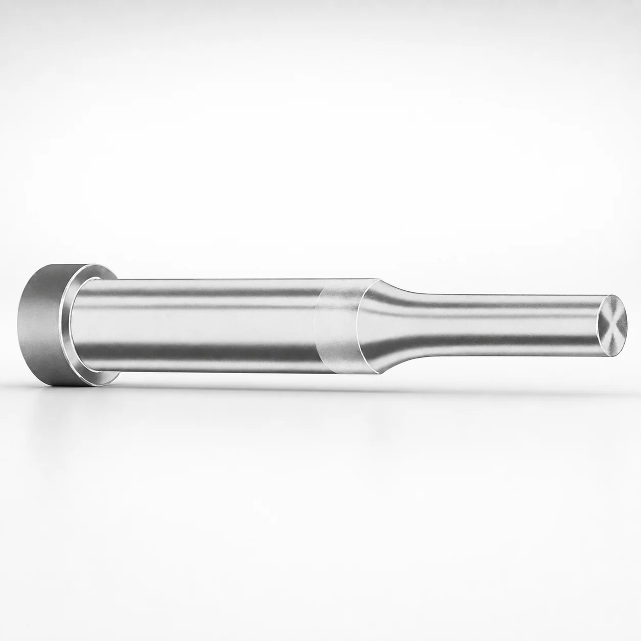
Inch Standard XNP Coated Regular Punches
Regular punches (inch standard) with XNP coating are designed for stable forming performance in punching dies, offering better resistance to abrasion and degradation under production loads.
- XNP coating supports longer punch life in repetitive stamping and die service
- Inch-standard punch geometry for consistent fit within typical tooling stacks
- Optional tip profiles provide controlled cutting engagement for different workpiece requirements
- DAYTON Lamina standardized part numbering simplifies identification and procurement
Specifications
882 configurations available
| Tip shape | D (Shank dia.) (in) | Standard [S] Point Length B & L (Length) (coded inch) | Alternate [B] Point Length B & L (Length) (coded inch) | Alternate [C] Point Length B & L (Length) (coded inch) | Alternate [D] Point Length B & L (Length) (coded inch) | Alternate [E] Point Length B & L (Length) (coded inch) | P Dimension (in) | W Dimension (in) | R Dimension (in) |
|---|---|---|---|---|---|---|---|---|---|
| H | 12(0.1250") | - | 150 ~ 400 | - | - | - | 0.062 ~ 0.125 | 0.062 ~ 0.125 | - |
| H | 12(0.1250") | 150 ~ 400 | - | - | - | - | 0.062 ~ 0.125 | 0.062 ~ 0.125 | - |
| H | 18(0.1875") | - | 150 ~ 500 | - | - | - | 0.062 ~ 0.1875 | 0.062 ~ 0.1875 | - |
| H | 18(0.1875") | 150 ~ 500 | - | - | - | - | 0.062 ~ 0.1875 | 0.062 ~ 0.1875 | - |
| H | 25(0.2500") | - | 150 ~ 600 | - | - | - | 0.062 ~ 0.25 | 0.062 ~ 0.0929 | - |
| H | 25(0.2500") | - | 150 ~ 600 | - | - | - | 0.062 ~ 0.25 | 0.093 ~ 0.25 | - |
| H | 25(0.2500") | 150 ~ 600 | - | - | - | - | 0.062 ~ 0.25 | 0.062 ~ 0.0929 | - |
| H | 25(0.2500") | 150 ~ 600 | - | - | - | - | 0.062 ~ 0.25 | 0.093 ~ 0.25 | - |
| H | 31(0.3125") | - | 150 ~ 600 | - | - | - | 0.062 ~ 0.3125 | 0.062 ~ 0.1249 | - |
| H | 31(0.3125") | - | 150 ~ 600 | - | - | - | 0.062 ~ 0.3125 | 0.125 ~ 0.3125 | - |
| H | 31(0.3125") | - | - | 175 ~ 600 | - | - | 0.062 ~ 0.3125 | 0.062 ~ 0.1249 | - |
| H | 31(0.3125") | - | - | 175 ~ 600 | - | - | 0.062 ~ 0.3125 | 0.125 ~ 0.3125 | - |
| H | 31(0.3125") | 150 ~ 600 | - | - | - | - | 0.062 ~ 0.3125 | 0.062 ~ 0.1249 | - |
| H | 31(0.3125") | 150 ~ 600 | - | - | - | - | 0.062 ~ 0.3125 | 0.125 ~ 0.3125 | - |
| H | 37(0.3750") | - | 175 ~ 600 | - | - | - | 0.08 ~ 0.375 | 0.08 ~ 0.1869 | - |
| H | 37(0.3750") | - | 175 ~ 600 | - | - | - | 0.08 ~ 0.375 | 0.187 ~ 0.375 | - |
| H | 37(0.3750") | - | - | 175 ~ 600 | - | - | 0.08 ~ 0.375 | 0.08 ~ 0.1869 | - |
| H | 37(0.3750") | - | - | 175 ~ 600 | - | - | 0.08 ~ 0.375 | 0.187 ~ 0.375 | - |
| H | 37(0.3750") | - | - | - | 200 ~ 600 | - | 0.08 ~ 0.375 | 0.08 ~ 0.1869 | - |
| H | 37(0.3750") | - | - | - | 200 ~ 600 | - | 0.08 ~ 0.375 | 0.187 ~ 0.375 | - |
| H | 37(0.3750") | 175 ~ 600 | - | - | - | - | 0.08 ~ 0.375 | 0.08 ~ 0.1869 | - |
| H | 37(0.3750") | 175 ~ 600 | - | - | - | - | 0.08 ~ 0.375 | 0.187 ~ 0.375 | - |
| H | 43(0.4375") | - | - | 200 ~ 700 | - | - | 0.158 ~ 0.4374 | 0.158 ~ 0.1869 | - |
| H | 43(0.4375") | - | - | 200 ~ 700 | - | - | 0.158 ~ 0.4374 | 0.187 ~ 0.4374 | - |
| H | 43(0.4375") | - | - | - | 200 ~ 700 | - | 0.158 ~ 0.4374 | 0.158 ~ 0.1869 | - |
| H | 43(0.4375") | - | - | - | 200 ~ 700 | - | 0.158 ~ 0.4374 | 0.187 ~ 0.4374 | - |
| H | 43(0.4375") | 200 ~ 700 | - | - | - | - | 0.158 ~ 0.4374 | 0.158 ~ 0.1869 | - |
| H | 43(0.4375") | 200 ~ 700 | - | - | - | - | 0.158 ~ 0.4374 | 0.187 ~ 0.4374 | - |
| H | 50(0.5000") | - | - | 200 ~ 700 | - | - | 0.158 ~ 0.5 | 0.158 ~ 0.1869 | - |
| H | 50(0.5000") | - | - | 200 ~ 700 | - | - | 0.158 ~ 0.5 | 0.187 ~ 0.5 | - |
| H | 50(0.5000") | - | - | - | 200 ~ 700 | - | 0.158 ~ 0.5 | 0.158 ~ 0.1869 | - |
| H | 50(0.5000") | - | - | - | 200 ~ 700 | - | 0.158 ~ 0.5 | 0.187 ~ 0.5 | - |
| H | 50(0.5000") | 200 ~ 700 | - | - | - | - | 0.158 ~ 0.5 | 0.158 ~ 0.1869 | - |
| H | 50(0.5000") | 200 ~ 700 | - | - | - | - | 0.158 ~ 0.5 | 0.187 ~ 0.5 | - |
| H | 62(0.6250") | - | - | - | 225 ~ 700 | - | 0.235 ~ 0.625 | 0.25 ~ 0.625 | - |
| H | 62(0.6250") | - | - | - | 225 ~ 700 | - | 0.235 ~ 0.625 | 0.235 ~ 0.2499 | - |
| H | 62(0.6250") | - | - | - | - | 225 ~ 700 | 0.235 ~ 0.625 | 0.25 ~ 0.625 | - |
| H | 62(0.6250") | - | - | - | - | 225 ~ 700 | 0.235 ~ 0.625 | 0.235 ~ 0.2499 | - |
| H | 62(0.6250") | 225 ~ 700 | - | - | - | - | 0.235 ~ 0.625 | 0.25 ~ 0.625 | - |
| H | 62(0.6250") | 225 ~ 700 | - | - | - | - | 0.235 ~ 0.625 | 0.235 ~ 0.2499 | - |
| H | 75(0.7500") | - | - | - | 225 ~ 700 | - | 0.235 ~ 0.75 | 0.235 ~ 0.3119 | - |
| H | 75(0.7500") | - | - | - | 225 ~ 700 | - | 0.235 ~ 0.75 | 0.312 ~ 0.75 | - |
| H | 75(0.7500") | - | - | - | - | 225 ~ 700 | 0.235 ~ 0.75 | 0.235 ~ 0.3119 | - |
| H | 75(0.7500") | - | - | - | - | 225 ~ 700 | 0.235 ~ 0.75 | 0.312 ~ 0.75 | - |
| H | 75(0.7500") | 225 ~ 700 | - | - | - | - | 0.235 ~ 0.75 | 0.235 ~ 0.3119 | - |
| H | 75(0.7500") | 225 ~ 700 | - | - | - | - | 0.235 ~ 0.75 | 0.312 ~ 0.75 | - |
| H | 87(0.8750") | - | - | - | 225 ~ 700 | - | 0.235 ~ 0.875 | 0.235 ~ 0.3119 | - |
| H | 87(0.8750") | - | - | - | 225 ~ 700 | - | 0.235 ~ 0.875 | 0.312 ~ 0.875 | - |
| H | 87(0.8750") | - | - | - | - | 225 ~ 700 | 0.235 ~ 0.875 | 0.235 ~ 0.3119 | - |
| H | 87(0.8750") | - | - | - | - | 225 ~ 700 | 0.235 ~ 0.875 | 0.312 ~ 0.875 | - |
Product Guide
Application Scenarios+
These inch-standard regular punches are used in progressive and single-station punching dies where repeatable cutting engagement and stable forming are required. The XNP coating is particularly suited for high-cycle stamping because it helps resist abrasion and reduces performance loss from tool-to-work contact.
- Automotive metal stamping: employ with H, J, K, L, N, O, R, V, X, or Z tip shapes to tune cutting geometry for housings and bracket features; the regular punch geometry supports consistent alignment in typical die layouts.
- Appliance and enclosure fabrication: suitable for producing holes and slots in sheet materials where the punch experiences frequent re-sharpening cycles; XNP coating supports longer run times under production load.
- Industrial connector and terminal punching: use alternate point-length ranges to match cavity depth requirements and maintain controlled bite, improving dimensional stability during repetitive operations.
For all cases, the inch sizing range and coded point length options make it easier to select a punch that fits established tooling stacks while benefiting from improved wear resistance.
Material & Process Details+
Material and heat-treatment specifics are not provided in the available product data for this series. What can be stated from the specification is the functional surface condition: XNP coating, which is used to improve wear resistance and reduce degradation during repetitive punching.
- XNP coating (functional emphasis): enhances resistance to abrasion at the punch tip and improves tool life in high-cycle stamping environments.
- Tip-shape selection vs. performance trade-offs: sharper or more aggressive tip profiles (selected via H/J/K/L/N/O/R/V/X/Y/Z) generally increase cutting engagement and may increase sensitivity to wear; XNP coating helps mitigate this by protecting the contact area.
When comparing materials or treatments for similar punches, engineers typically balance hardness (for wear) against toughness (for chipping resistance). Since the steel grade and HRC are not listed here, final hardness and toughness confirmation should be verified with the supplier’s technical documentation for the selected option.
Sizing & Selection Guide+
Correct sizing for this inch-standard punch series starts with selecting the correct shank diameter D and then matching the point length B & L (coded inch) to the die/cavity depth where cutting takes place.
- Shank diameter (D): choose D in the range 12 ~ 250 in to match the guide/bushing and press-fit or sliding requirements in your tooling stack.
- Standard point length: the S point length B & L is coded 150 ~ 250.
- Alternate point lengths: use the coded ranges listed for B, C, D, and E (e.g., up to 150 ~ 600, 150 ~ 700, and 250 ~ 700) when your die requires greater penetration or clearance.
Also confirm the P dimension (0.042 ~ 1.625 in) and W dimension (0.062 ~ 0.5 in) for tip geometry compatibility, and verify the R dimension (0.007 ~ 0.007 in) for corner radius matching to your shearing condition. Tolerances and fit depend on your bushing/guidance design; therefore, validate fit class and seating depth after selecting the coded lengths.
Frequently Asked Questions
Which tip shape options (H/J/K/L/N/O/R/V/X/Y/Z) should I choose for controlled punching engagement?+
Select the tip shape based on the cutting geometry you need for your sheet workpiece and required shearing performance. This series supports multiple tip shapes (H, J, K, L, N, O, R, V, X, Y, Z) so you can tune engagement without changing the inch-standard punch layout.
Use XNP coating to help maintain wear resistance at the contact area during repetitive production runs.
How do I match the punch length to my die cavity/core setup using the coded B & L point-length ranges?+
For this series, the S point length (B & L) is coded 150 ~ 250 inch values. If your die requires more reach, choose one of the alternate sets: B (150~400/500/600, 175~600, etc.), C (175~600, 200~700), D (200~600, 225~700), or E (225~700, 250~700).
Confirm the selected coded length corresponds to the required penetration and clearance so the punch maintains stable cutting engagement.
What shank diameter (D) range is available, and how should it be verified for tooling stack fit?+
The available shank diameter D range is 12 ~ 250 in for this inch-standard regular punch series. Verify the selected D matches your die guide/bushing bore and the intended fit type (sliding vs. interference/retention as designed).
After choosing D, re-check point length B & L to ensure the punch tip position aligns with your die/cavity shearing zone.
How does the XNP coating improve tool life for repeated stamping operations?+
This series specifies XNP coating to improve resistance to abrasion and degradation under production loads. In practice, the coating helps the punch maintain performance during high-cycle punching where tip and land surfaces continuously contact the work material.
Pair the XNP coating with the correct tip shape and coded point length to maintain consistent cutting engagement and reduce the rate of surface wear.
Are dimensions like P, W, and R configurable for geometry compatibility across different applications?+
Yes. The specification provides geometry ranges for P = 0.042 ~ 1.625 in, W = 0.062 ~ 0.5 in, and R = 0.007 ~ 0.007 in for this series. When selecting a punch, compare these dimensions against your die design constraints (e.g., tip corner compatibility and clearance requirements).
Because tolerance/fit depends on your die components, validate seating and clearance during tooling build-up.
Related Products






Need Custom Specifications?
Our engineering team can help with custom configurations, material selection, and volume pricing.