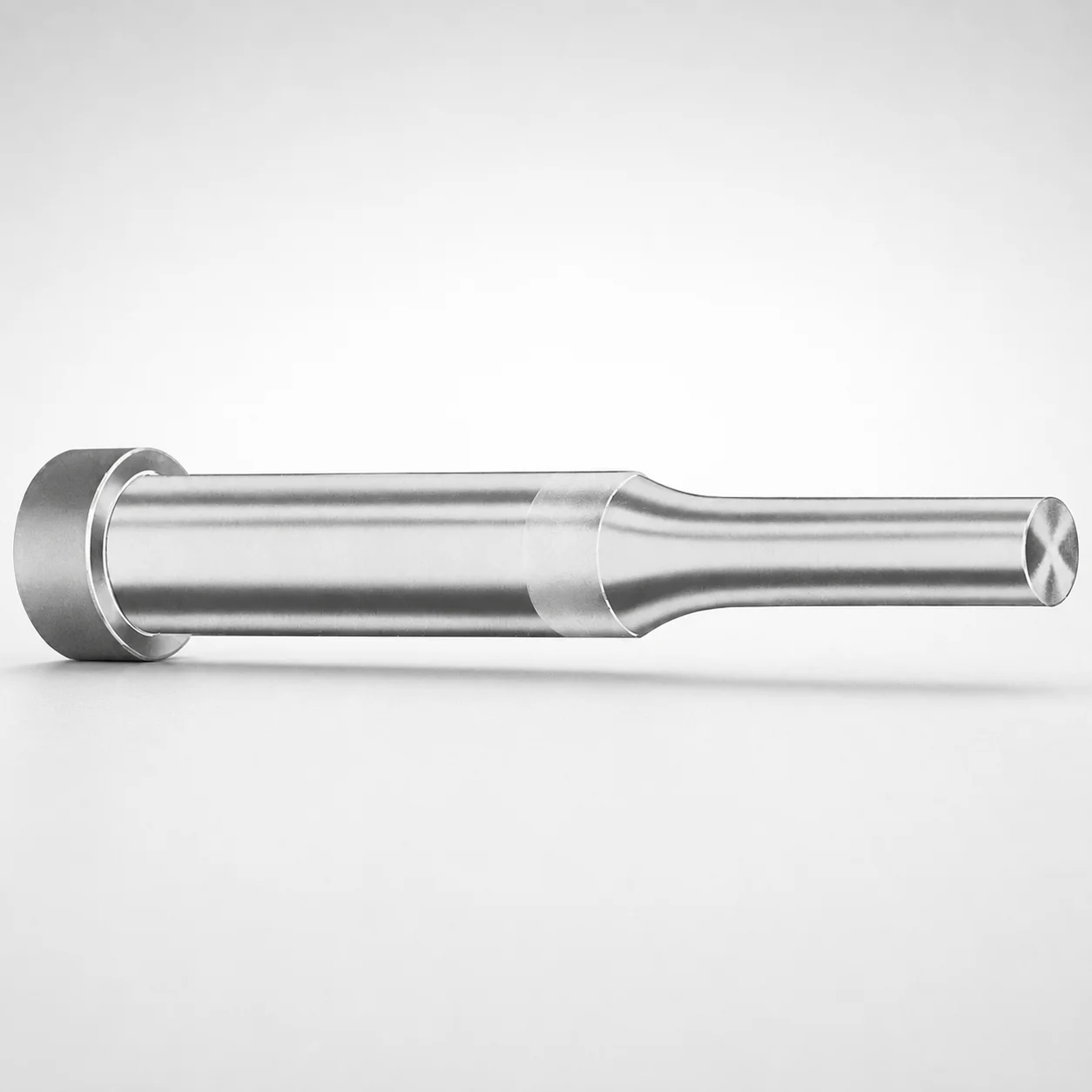
Inch Regular Punches XNM Coating
Inch regular punches XNM coating are designed for reliable material piercing and punching in production tooling, using an engineered XNM coating system to support stable wear behavior. Built for compatibility with standard punch assemblies and efficient changeovers.
- XNM coating helps improve surface durability for punch operation
- Inch punch format supports efficient integration into existing die sets
- Options for tip geometry support selection across different workpieces
- Dayton LAMINA standardized part numbering simplifies ordering workflow
Specifications
662 configurations available
| Tip shape | D (Shank dia.) (in) | Standard [S] Point Length B & L (Length) (coded inch) | Alternate [B] Point Length B & L (Length) (coded inch) | Alternate [C] Point Length B & L (Length) (coded inch) | Alternate [D] Point Length B & L (Length) (coded inch) | Alternate [E] Point Length B & L (Length) (coded inch) | P Dimension (in) | W Dimension (in) | R Dimension (in) |
|---|---|---|---|---|---|---|---|---|---|
| H | 12(0.1250") | - | 150 ~ 400 | - | - | - | 0.062 ~ 0.125 | 0.062 ~ 0.125 | - |
| H | 12(0.1250") | 150 ~ 400 | - | - | - | - | 0.062 ~ 0.125 | 0.062 ~ 0.125 | - |
| H | 18(0.1875") | - | 150 ~ 500 | - | - | - | 0.062 ~ 0.1875 | 0.062 ~ 0.1875 | - |
| H | 18(0.1875") | 150 ~ 500 | - | - | - | - | 0.062 ~ 0.1875 | 0.062 ~ 0.1875 | - |
| H | 25(0.2500") | - | 150 ~ 600 | - | - | - | 0.062 ~ 0.25 | 0.062 ~ 0.0929 | - |
| H | 25(0.2500") | - | 150 ~ 600 | - | - | - | 0.062 ~ 0.25 | 0.093 ~ 0.25 | - |
| H | 25(0.2500") | 150 ~ 600 | - | - | - | - | 0.062 ~ 0.25 | 0.062 ~ 0.0929 | - |
| H | 25(0.2500") | 150 ~ 600 | - | - | - | - | 0.062 ~ 0.25 | 0.093 ~ 0.25 | - |
| H | 31(0.3125") | - | 150 ~ 600 | - | - | - | 0.062 ~ 0.3125 | 0.062 ~ 0.1249 | - |
| H | 31(0.3125") | - | 150 ~ 600 | - | - | - | 0.062 ~ 0.3125 | 0.125 ~ 0.3125 | - |
| H | 31(0.3125") | - | - | 175 ~ 600 | - | - | 0.062 ~ 0.3125 | 0.062 ~ 0.1249 | - |
| H | 31(0.3125") | - | - | 175 ~ 600 | - | - | 0.062 ~ 0.3125 | 0.125 ~ 0.3125 | - |
| H | 31(0.3125") | 150 ~ 600 | - | - | - | - | 0.062 ~ 0.3125 | 0.062 ~ 0.1249 | - |
| H | 31(0.3125") | 150 ~ 600 | - | - | - | - | 0.062 ~ 0.3125 | 0.125 ~ 0.3125 | - |
| H | 37(0.3750") | - | 175 ~ 600 | - | - | - | 0.08 ~ 0.375 | 0.08 ~ 0.1869 | - |
| H | 37(0.3750") | - | 175 ~ 600 | - | - | - | 0.08 ~ 0.375 | 0.187 ~ 0.375 | - |
| H | 37(0.3750") | - | - | 175 ~ 600 | - | - | 0.08 ~ 0.375 | 0.08 ~ 0.1869 | - |
| H | 37(0.3750") | - | - | 175 ~ 600 | - | - | 0.08 ~ 0.375 | 0.187 ~ 0.375 | - |
| H | 37(0.3750") | - | - | - | 200 ~ 600 | - | 0.08 ~ 0.375 | 0.08 ~ 0.1869 | - |
| H | 37(0.3750") | - | - | - | 200 ~ 600 | - | 0.08 ~ 0.375 | 0.187 ~ 0.375 | - |
| H | 37(0.3750") | 175 ~ 600 | - | - | - | - | 0.08 ~ 0.375 | 0.08 ~ 0.1869 | - |
| H | 37(0.3750") | 175 ~ 600 | - | - | - | - | 0.08 ~ 0.375 | 0.187 ~ 0.375 | - |
| H | 43(0.4375") | - | - | 200 ~ 700 | - | - | 0.158 ~ 0.4374 | 0.158 ~ 0.1869 | - |
| H | 43(0.4375") | - | - | 200 ~ 700 | - | - | 0.158 ~ 0.4374 | 0.187 ~ 0.4374 | - |
| H | 43(0.4375") | - | - | - | 200 ~ 700 | - | 0.158 ~ 0.4374 | 0.158 ~ 0.1869 | - |
| H | 43(0.4375") | - | - | - | 200 ~ 700 | - | 0.158 ~ 0.4374 | 0.187 ~ 0.4374 | - |
| H | 43(0.4375") | 200 ~ 700 | - | - | - | - | 0.158 ~ 0.4374 | 0.158 ~ 0.1869 | - |
| H | 43(0.4375") | 200 ~ 700 | - | - | - | - | 0.158 ~ 0.4374 | 0.187 ~ 0.4374 | - |
| H | 50(0.5000") | - | - | 200 ~ 700 | - | - | 0.158 ~ 0.5 | 0.158 ~ 0.1869 | - |
| H | 50(0.5000") | - | - | 200 ~ 700 | - | - | 0.158 ~ 0.5 | 0.187 ~ 0.5 | - |
| H | 50(0.5000") | - | - | - | 200 ~ 700 | - | 0.158 ~ 0.5 | 0.158 ~ 0.1869 | - |
| H | 50(0.5000") | - | - | - | 200 ~ 700 | - | 0.158 ~ 0.5 | 0.187 ~ 0.5 | - |
| H | 50(0.5000") | 200 ~ 700 | - | - | - | - | 0.158 ~ 0.5 | 0.158 ~ 0.1869 | - |
| H | 50(0.5000") | 200 ~ 700 | - | - | - | - | 0.158 ~ 0.5 | 0.187 ~ 0.5 | - |
| H | 62(0.6250") | - | - | - | 225 ~ 700 | - | 0.235 ~ 0.625 | 0.25 ~ 0.625 | - |
| H | 62(0.6250") | - | - | - | 225 ~ 700 | - | 0.235 ~ 0.625 | 0.235 ~ 0.2499 | - |
| H | 62(0.6250") | - | - | - | - | 225 ~ 700 | 0.235 ~ 0.625 | 0.25 ~ 0.625 | - |
| H | 62(0.6250") | - | - | - | - | 225 ~ 700 | 0.235 ~ 0.625 | 0.235 ~ 0.2499 | - |
| H | 62(0.6250") | 225 ~ 700 | - | - | - | - | 0.235 ~ 0.625 | 0.25 ~ 0.625 | - |
| H | 62(0.6250") | 225 ~ 700 | - | - | - | - | 0.235 ~ 0.625 | 0.235 ~ 0.2499 | - |
| H | 75(0.7500") | - | - | - | 225 ~ 700 | - | 0.235 ~ 0.75 | 0.235 ~ 0.3119 | - |
| H | 75(0.7500") | - | - | - | 225 ~ 700 | - | 0.235 ~ 0.75 | 0.312 ~ 0.75 | - |
| H | 75(0.7500") | - | - | - | - | 225 ~ 700 | 0.235 ~ 0.75 | 0.235 ~ 0.3119 | - |
| H | 75(0.7500") | - | - | - | - | 225 ~ 700 | 0.235 ~ 0.75 | 0.312 ~ 0.75 | - |
| H | 75(0.7500") | 225 ~ 700 | - | - | - | - | 0.235 ~ 0.75 | 0.235 ~ 0.3119 | - |
| H | 75(0.7500") | 225 ~ 700 | - | - | - | - | 0.235 ~ 0.75 | 0.312 ~ 0.75 | - |
| H | 87(0.8750") | - | - | - | 225 ~ 700 | - | 0.235 ~ 0.875 | 0.235 ~ 0.3119 | - |
| H | 87(0.8750") | - | - | - | 225 ~ 700 | - | 0.235 ~ 0.875 | 0.312 ~ 0.875 | - |
| H | 87(0.8750") | - | - | - | - | 225 ~ 700 | 0.235 ~ 0.875 | 0.235 ~ 0.3119 | - |
| H | 87(0.8750") | - | - | - | - | 225 ~ 700 | 0.235 ~ 0.875 | 0.312 ~ 0.875 | - |
Product Guide
Application Scenarios+
This inch regular punch with an XNM coating is used in injection and die-cut tooling where repeatable piercing and punching performance is required across production runs. The coating is suited for applications that experience sliding wear at the punch tip and shank, helping maintain stable cutting edges and surface durability.
- Automotive and industrial connector stampings: Select among available tip shapes (H, J, K, L, N, O, R, V, X, Y, Z) to match hole geometry needs while using the inch punch format for straightforward integration into standard punch assemblies.
- Electronics enclosures and bracket blanking: Use the defined shank diameter range (12–125 in) and the coded point length options (standard and alternate ranges) to align with your die clearance and stripping requirements.
- General manufacturing sheet/laminate punching: The variant supports efficient changeovers in tooling because it follows standardized, coded sizing conventions for quick selection and replacement.
Material & Process Details+
The provided specifications specify an XNM coating system for this punch variant, optimized for stable wear behavior at the working surfaces. However, the input data does not include the underlying steel grade, hardening route, or measured hardness (HRC), so those details cannot be stated reliably.
- Coating function: XNM is intended to improve punch surface durability and reduce wear during repeated punching cycles.
- Wear vs. toughness trade-off: Coatings typically enhance surface resistance while relying on the base steel for toughness; choosing the correct tip geometry helps manage localized stress at the point.
- Heat treatment: Not specified in the provided data; request steel and heat-treatment documentation if hardness verification is required for your process.
Sizing & Selection Guide+
Select dimensions by matching your punch point geometry and shank fit to the die setup, starting with the required tip shape and then confirming the shank and length ranges. This series supports tip shapes H, J, K, L, N, O, R, V, X, Y, Z and a shank diameter D (in) = 12 ~ 125.
- Point length (B & L) selection: Use the Standard [S] Point Length coded inch range 150 ~ 250 or choose alternates such as 150–400 / 150–500 / 150–600 / 175–600 (Alternate [B]), 175–600 / 200–700 (Alternate [C]), 200–600 / 200–700 / 225–700 (Alternate [D]), and 225–700 / 250–700 (Alternate [E]).
- Profile dimensions: Confirm P = 0.042 ~ 0.625 in, W = 0.062 ~ 0.312 in, and R = 0.007 ~ 0.007 in to ensure the tip matches your cavity/core and cutting edge requirements.
- Tolerance/fit: No tolerance values are provided in the input; validate fit with your punch guide/bushing clearance and die opening tolerances using your supplier’s drawings.
Frequently Asked Questions
Which tip shapes (H/J/K/…/Z) should I choose for different hole geometries?+
This series offers tip shapes H, J, K, L, N, O, R, V, X, Y, Z, allowing you to align the punch point profile with your target hole geometry and cutting conditions. Select the tip shape first, then verify the matching profile dimensions P (0.042–0.625 in) and W (0.062–0.312 in) against your die opening requirements.
How do I choose between standard [S] and alternate point length ranges (150–250 vs 150–400…700)?+
Use Standard [S] Point Length coded inch range 150–250 when your punch length is within that window. For longer in-die engagement or specific stripping/stack-up needs, use the alternate ranges: [B] 150–400/150–500/150–600/175–600, [C] 175–600/200–700, [D] 200–600/200–700/225–700, or [E] 225–700/250–700.
What shank diameter range is available for this inch regular punch?+
The available shank diameter range is D (in) = 12 ~ 125. Confirm that this D size matches your punch holder/punch guide bushing bore requirements for stable support during punching cycles.
Does the XNM coating affect die wear or punch life in high-cycle production?+
The input data states that the XNM coating system is engineered to support stable wear behavior and improved punch surface durability. This makes it relevant for high-cycle piercing where sliding wear at the working surfaces can shorten tool life.
Are material grade and hardness (HRC) specified for this punch?+
No steel grade or heat-treatment/hardness values (HRC) are included in the provided specifications. The only explicit material-related information provided is the XNM coating, so hardness verification and base-steel documentation should be requested if required for your process qualification.
Related Products






Need Custom Specifications?
Our engineering team can help with custom configurations, material selection, and volume pricing.