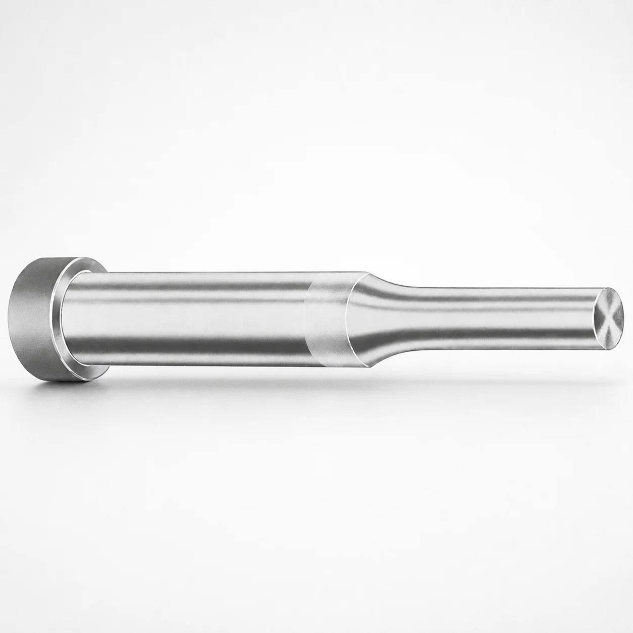
Inch Regular Punches (XNAD Coating) by DAYTON
Regular Punches (Inch) (DAYTON, XNAD coating) are designed to deliver stable punch performance in high-cycle die applications. The engineered coating helps reduce wear for more consistent forming and punching.
- XNAD coating supports long service life under repeated punching cycles
- Optimized for close-tolerance die use with standardized punch geometry
- Inch series punch format helps streamline selection for North American tooling
- Typical use in progressive dies, stamping, and precision punching operations
Specifications
882 configurations available
| Tip shape | D (Shank dia.) (in) | Standard [S] Point Length B & L (Length) (coded inch) | Alternate [B] Point Length B & L (Length) (coded inch) | Alternate [C] Point Length B & L (Length) (coded inch) | Alternate [D] Point Length B & L (Length) (coded inch) | Alternate [E] Point Length B & L (Length) (coded inch) | P Dimension (in) | W Dimension (in) | R Dimension (in) |
|---|---|---|---|---|---|---|---|---|---|
| H | 12(0.1250") | - | 150 ~ 400 | - | - | - | 0.062 ~ 0.125 | 0.062 ~ 0.125 | - |
| H | 12(0.1250") | 150 ~ 400 | - | - | - | - | 0.062 ~ 0.125 | 0.062 ~ 0.125 | - |
| H | 18(0.1875") | - | 150 ~ 500 | - | - | - | 0.062 ~ 0.1875 | 0.062 ~ 0.1875 | - |
| H | 18(0.1875") | 150 ~ 500 | - | - | - | - | 0.062 ~ 0.1875 | 0.062 ~ 0.1875 | - |
| H | 25(0.2500") | - | 150 ~ 600 | - | - | - | 0.062 ~ 0.25 | 0.062 ~ 0.0929 | - |
| H | 25(0.2500") | - | 150 ~ 600 | - | - | - | 0.062 ~ 0.25 | 0.093 ~ 0.25 | - |
| H | 25(0.2500") | 150 ~ 600 | - | - | - | - | 0.062 ~ 0.25 | 0.062 ~ 0.0929 | - |
| H | 25(0.2500") | 150 ~ 600 | - | - | - | - | 0.062 ~ 0.25 | 0.093 ~ 0.25 | - |
| H | 31(0.3125") | - | 150 ~ 600 | - | - | - | 0.062 ~ 0.3125 | 0.062 ~ 0.1249 | - |
| H | 31(0.3125") | - | 150 ~ 600 | - | - | - | 0.062 ~ 0.3125 | 0.125 ~ 0.3125 | - |
| H | 31(0.3125") | - | - | 175 ~ 600 | - | - | 0.062 ~ 0.3125 | 0.062 ~ 0.1249 | - |
| H | 31(0.3125") | - | - | 175 ~ 600 | - | - | 0.062 ~ 0.3125 | 0.125 ~ 0.3125 | - |
| H | 31(0.3125") | 150 ~ 600 | - | - | - | - | 0.062 ~ 0.3125 | 0.062 ~ 0.1249 | - |
| H | 31(0.3125") | 150 ~ 600 | - | - | - | - | 0.062 ~ 0.3125 | 0.125 ~ 0.3125 | - |
| H | 37(0.3750") | - | 175 ~ 600 | - | - | - | 0.08 ~ 0.375 | 0.08 ~ 0.1869 | - |
| H | 37(0.3750") | - | 175 ~ 600 | - | - | - | 0.08 ~ 0.375 | 0.187 ~ 0.375 | - |
| H | 37(0.3750") | - | - | 175 ~ 600 | - | - | 0.08 ~ 0.375 | 0.08 ~ 0.1869 | - |
| H | 37(0.3750") | - | - | 175 ~ 600 | - | - | 0.08 ~ 0.375 | 0.187 ~ 0.375 | - |
| H | 37(0.3750") | - | - | - | 200 ~ 600 | - | 0.08 ~ 0.375 | 0.08 ~ 0.1869 | - |
| H | 37(0.3750") | - | - | - | 200 ~ 600 | - | 0.08 ~ 0.375 | 0.187 ~ 0.375 | - |
| H | 37(0.3750") | 175 ~ 600 | - | - | - | - | 0.08 ~ 0.375 | 0.08 ~ 0.1869 | - |
| H | 37(0.3750") | 175 ~ 600 | - | - | - | - | 0.08 ~ 0.375 | 0.187 ~ 0.375 | - |
| H | 43(0.4375") | - | - | 200 ~ 700 | - | - | 0.158 ~ 0.4374 | 0.158 ~ 0.1869 | - |
| H | 43(0.4375") | - | - | 200 ~ 700 | - | - | 0.158 ~ 0.4374 | 0.187 ~ 0.4374 | - |
| H | 43(0.4375") | - | - | - | 200 ~ 700 | - | 0.158 ~ 0.4374 | 0.158 ~ 0.1869 | - |
| H | 43(0.4375") | - | - | - | 200 ~ 700 | - | 0.158 ~ 0.4374 | 0.187 ~ 0.4374 | - |
| H | 43(0.4375") | 200 ~ 700 | - | - | - | - | 0.158 ~ 0.4374 | 0.158 ~ 0.1869 | - |
| H | 43(0.4375") | 200 ~ 700 | - | - | - | - | 0.158 ~ 0.4374 | 0.187 ~ 0.4374 | - |
| H | 50(0.5000") | - | - | 200 ~ 700 | - | - | 0.158 ~ 0.5 | 0.158 ~ 0.1869 | - |
| H | 50(0.5000") | - | - | 200 ~ 700 | - | - | 0.158 ~ 0.5 | 0.187 ~ 0.5 | - |
| H | 50(0.5000") | - | - | - | 200 ~ 700 | - | 0.158 ~ 0.5 | 0.158 ~ 0.1869 | - |
| H | 50(0.5000") | - | - | - | 200 ~ 700 | - | 0.158 ~ 0.5 | 0.187 ~ 0.5 | - |
| H | 50(0.5000") | 200 ~ 700 | - | - | - | - | 0.158 ~ 0.5 | 0.158 ~ 0.1869 | - |
| H | 50(0.5000") | 200 ~ 700 | - | - | - | - | 0.158 ~ 0.5 | 0.187 ~ 0.5 | - |
| H | 62(0.6250") | - | - | - | 225 ~ 700 | - | 0.235 ~ 0.625 | 0.25 ~ 0.625 | - |
| H | 62(0.6250") | - | - | - | 225 ~ 700 | - | 0.235 ~ 0.625 | 0.235 ~ 0.2499 | - |
| H | 62(0.6250") | - | - | - | - | 225 ~ 700 | 0.235 ~ 0.625 | 0.25 ~ 0.625 | - |
| H | 62(0.6250") | - | - | - | - | 225 ~ 700 | 0.235 ~ 0.625 | 0.235 ~ 0.2499 | - |
| H | 62(0.6250") | 225 ~ 700 | - | - | - | - | 0.235 ~ 0.625 | 0.25 ~ 0.625 | - |
| H | 62(0.6250") | 225 ~ 700 | - | - | - | - | 0.235 ~ 0.625 | 0.235 ~ 0.2499 | - |
| H | 75(0.7500") | - | - | - | 225 ~ 700 | - | 0.235 ~ 0.75 | 0.235 ~ 0.3119 | - |
| H | 75(0.7500") | - | - | - | 225 ~ 700 | - | 0.235 ~ 0.75 | 0.312 ~ 0.75 | - |
| H | 75(0.7500") | - | - | - | - | 225 ~ 700 | 0.235 ~ 0.75 | 0.235 ~ 0.3119 | - |
| H | 75(0.7500") | - | - | - | - | 225 ~ 700 | 0.235 ~ 0.75 | 0.312 ~ 0.75 | - |
| H | 75(0.7500") | 225 ~ 700 | - | - | - | - | 0.235 ~ 0.75 | 0.235 ~ 0.3119 | - |
| H | 75(0.7500") | 225 ~ 700 | - | - | - | - | 0.235 ~ 0.75 | 0.312 ~ 0.75 | - |
| H | 87(0.8750") | - | - | - | 225 ~ 700 | - | 0.235 ~ 0.875 | 0.235 ~ 0.3119 | - |
| H | 87(0.8750") | - | - | - | 225 ~ 700 | - | 0.235 ~ 0.875 | 0.312 ~ 0.875 | - |
| H | 87(0.8750") | - | - | - | - | 225 ~ 700 | 0.235 ~ 0.875 | 0.235 ~ 0.3119 | - |
| H | 87(0.8750") | - | - | - | - | 225 ~ 700 | 0.235 ~ 0.875 | 0.312 ~ 0.875 | - |
Product Guide
Application Scenarios+
This inch-format standard punch set is used in production punching and die work where stable performance over high cycle counts is required. The DAYTON XNAD coating is suited to applications that demand improved wear resistance, helping maintain consistent cutting geometry and forming results.
- Progressive stamping dies: Use the standardized punch geometry to support repeatable hole/pierce operations in tight tool layouts; the coating helps reduce abrasive and adhesive wear during continuous cycling.
- Precision punching and die work: Choose the appropriate tip shape to match the feature profile while benefiting from the coating’s wear-reduction effect for longer maintenance intervals.
- Automotive and appliance components: In long runs of stamped parts, the coated punches help sustain punch performance under repeated impacts, improving consistency across shifts.
Tip shape options (H, J, K, L, N, O, R, V, X, Y, Z) allow engineers to align the punch nose profile with cavity/core requirements while keeping selection streamlined for North American inch tooling.
Material & Process Details+
The provided specification focuses on the DAYTON XNAD coating and dimensional ranges rather than a base steel grade or hardness. For this reason, the material section should be treated as coating- and process-oriented for wear performance in die work.
- XNAD coating (wear layer): Selected to improve wear resistance in high-cycle punching, supporting longer service life under repeated impacts and cutting friction.
- Manufacturing implication: In typical die-punch production, the punch body is machined to the required shank diameter and length codes, then the coated wear surface is applied to enhance resistance at the tip region.
- Trade-off: Coatings generally improve wear/abrasion resistance but require correct fit and alignment in the die to avoid edge chipping or premature coating damage.
If you need the exact base steel grade, hardness (HRC), and heat-treatment state for this specific series code, request the material certificate from Axiom Molds.
Sizing & Selection Guide+
Selection is driven by matching the punch shank diameter D (12 ~ 250 in) and the required point length to your die cavity/core layout. This inch series uses coded point length ranges for consistent procurement in North American tooling.
- Choose tip shape: Select from H, J, K, L, N, O, R, V, X, Y, Z to align with the desired cut geometry.
- Set shank diameter: Use D = 12 ~ 250 in (as specified) to ensure the punch fits the corresponding die guide/bushing ID with proper clearance.
- Select point length (B & L): Standard S point length is 150 ~ 250 (coded inch). Alternate options include 150~400, 150~500, 150~600, 175~600, 200~700, 225~700, and 250~700, depending on the alternate category (B/C/D/E).
- Verify related dimensions: Confirm P = 0.042 ~ 1.625 in, W = 0.062 ~ 0.5 in, and R = 0.007 in to maintain punch-tip edge formation requirements.
Because tolerances are not provided in the input data, validate fit and clearance against your die guide/bushing specification before final tooling build.
Frequently Asked Questions
Which punch tip shapes (H/J/K/L/N/O/R/V/X/Y/Z) should be selected for different punching edge profiles?+
How do I match the shank diameter D to my die guide or bushing to avoid misalignment wear?+
What point length options are available (standard S vs. alternate B/C/D/E), and how do they affect penetration depth?+
Do the provided P, W, and R dimensions constrain compatibility with existing tooling geometry?+
What benefit does the DAYTON XNAD coating provide for high-cycle die punching?+
Related Products






Need Custom Specifications?
Our engineering team can help with custom configurations, material selection, and volume pricing.