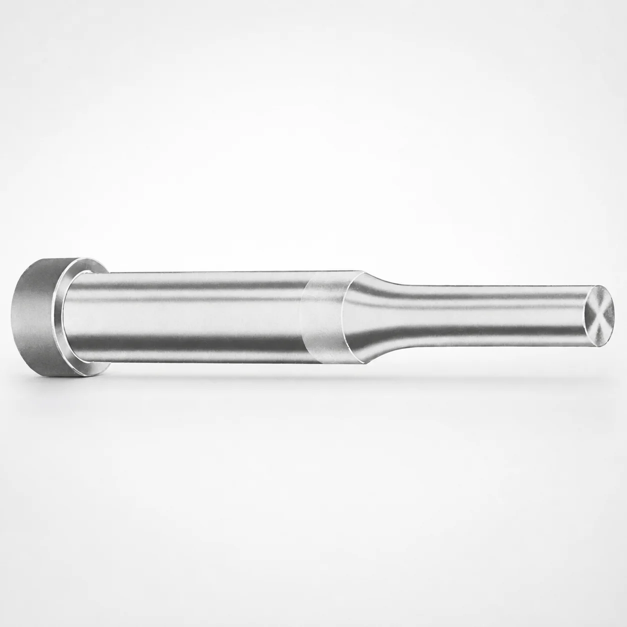
Inch XCN Coating Regular Punches
Inch XCN coating regular punches from DAYTON are designed for durable die and press applications where consistent material engagement is critical. The XCN-coated surface helps improve wear resistance for dependable punch performance in production.
- Wide tip shape selection: X, R, K, O, H, L, J, N, V, Y, Z for application fit
- Inch punch construction supports stable shank handling across a broad diameter range
- Coated punch face for longer service life under repeated forming cycles
- Typical use in stamping, punching, and die making for controlled part forming
Specifications
882 configurations available
| Tip shape | D (Shank dia.) (in) | Standard [S] Point Length B & L (Length) (coded inch) | Alternate [B] Point Length B & L (Length) (coded inch) | Alternate [C] Point Length B & L (Length) (coded inch) | Alternate [D] Point Length B & L (Length) (coded inch) | Alternate [E] Point Length B & L (Length) (coded inch) | P Dimension (in) | W Dimension (in) | R Dimension (in) |
|---|---|---|---|---|---|---|---|---|---|
| H | 12(0.1250") | - | 150 ~ 400 | - | - | - | 0.062 ~ 0.125 | 0.062 ~ 0.125 | - |
| H | 12(0.1250") | 150 ~ 400 | - | - | - | - | 0.062 ~ 0.125 | 0.062 ~ 0.125 | - |
| H | 18(0.1875") | - | 150 ~ 500 | - | - | - | 0.062 ~ 0.1875 | 0.062 ~ 0.1875 | - |
| H | 18(0.1875") | 150 ~ 500 | - | - | - | - | 0.062 ~ 0.1875 | 0.062 ~ 0.1875 | - |
| H | 25(0.2500") | - | 150 ~ 600 | - | - | - | 0.062 ~ 0.25 | 0.062 ~ 0.0929 | - |
| H | 25(0.2500") | - | 150 ~ 600 | - | - | - | 0.062 ~ 0.25 | 0.093 ~ 0.25 | - |
| H | 25(0.2500") | 150 ~ 600 | - | - | - | - | 0.062 ~ 0.25 | 0.062 ~ 0.0929 | - |
| H | 25(0.2500") | 150 ~ 600 | - | - | - | - | 0.062 ~ 0.25 | 0.093 ~ 0.25 | - |
| H | 31(0.3125") | - | 150 ~ 600 | - | - | - | 0.062 ~ 0.3125 | 0.062 ~ 0.1249 | - |
| H | 31(0.3125") | - | 150 ~ 600 | - | - | - | 0.062 ~ 0.3125 | 0.125 ~ 0.3125 | - |
| H | 31(0.3125") | - | - | 175 ~ 600 | - | - | 0.062 ~ 0.3125 | 0.062 ~ 0.1249 | - |
| H | 31(0.3125") | - | - | 175 ~ 600 | - | - | 0.062 ~ 0.3125 | 0.125 ~ 0.3125 | - |
| H | 31(0.3125") | 150 ~ 600 | - | - | - | - | 0.062 ~ 0.3125 | 0.062 ~ 0.1249 | - |
| H | 31(0.3125") | 150 ~ 600 | - | - | - | - | 0.062 ~ 0.3125 | 0.125 ~ 0.3125 | - |
| H | 37(0.3750") | - | 175 ~ 600 | - | - | - | 0.08 ~ 0.375 | 0.08 ~ 0.1869 | - |
| H | 37(0.3750") | - | 175 ~ 600 | - | - | - | 0.08 ~ 0.375 | 0.187 ~ 0.375 | - |
| H | 37(0.3750") | - | - | 175 ~ 600 | - | - | 0.08 ~ 0.375 | 0.08 ~ 0.1869 | - |
| H | 37(0.3750") | - | - | 175 ~ 600 | - | - | 0.08 ~ 0.375 | 0.187 ~ 0.375 | - |
| H | 37(0.3750") | - | - | - | 200 ~ 600 | - | 0.08 ~ 0.375 | 0.08 ~ 0.1869 | - |
| H | 37(0.3750") | - | - | - | 200 ~ 600 | - | 0.08 ~ 0.375 | 0.187 ~ 0.375 | - |
| H | 37(0.3750") | 175 ~ 600 | - | - | - | - | 0.08 ~ 0.375 | 0.08 ~ 0.1869 | - |
| H | 37(0.3750") | 175 ~ 600 | - | - | - | - | 0.08 ~ 0.375 | 0.187 ~ 0.375 | - |
| H | 43(0.4375") | - | - | 200 ~ 700 | - | - | 0.158 ~ 0.4374 | 0.158 ~ 0.1869 | - |
| H | 43(0.4375") | - | - | 200 ~ 700 | - | - | 0.158 ~ 0.4374 | 0.187 ~ 0.4374 | - |
| H | 43(0.4375") | - | - | - | 200 ~ 700 | - | 0.158 ~ 0.4374 | 0.158 ~ 0.1869 | - |
| H | 43(0.4375") | - | - | - | 200 ~ 700 | - | 0.158 ~ 0.4374 | 0.187 ~ 0.4374 | - |
| H | 43(0.4375") | 200 ~ 700 | - | - | - | - | 0.158 ~ 0.4374 | 0.158 ~ 0.1869 | - |
| H | 43(0.4375") | 200 ~ 700 | - | - | - | - | 0.158 ~ 0.4374 | 0.187 ~ 0.4374 | - |
| H | 50(0.5000") | - | - | 200 ~ 700 | - | - | 0.158 ~ 0.5 | 0.158 ~ 0.1869 | - |
| H | 50(0.5000") | - | - | 200 ~ 700 | - | - | 0.158 ~ 0.5 | 0.187 ~ 0.5 | - |
| H | 50(0.5000") | - | - | - | 200 ~ 700 | - | 0.158 ~ 0.5 | 0.158 ~ 0.1869 | - |
| H | 50(0.5000") | - | - | - | 200 ~ 700 | - | 0.158 ~ 0.5 | 0.187 ~ 0.5 | - |
| H | 50(0.5000") | 200 ~ 700 | - | - | - | - | 0.158 ~ 0.5 | 0.158 ~ 0.1869 | - |
| H | 50(0.5000") | 200 ~ 700 | - | - | - | - | 0.158 ~ 0.5 | 0.187 ~ 0.5 | - |
| H | 62(0.6250") | - | - | - | 225 ~ 700 | - | 0.235 ~ 0.625 | 0.25 ~ 0.625 | - |
| H | 62(0.6250") | - | - | - | 225 ~ 700 | - | 0.235 ~ 0.625 | 0.235 ~ 0.2499 | - |
| H | 62(0.6250") | - | - | - | - | 225 ~ 700 | 0.235 ~ 0.625 | 0.25 ~ 0.625 | - |
| H | 62(0.6250") | - | - | - | - | 225 ~ 700 | 0.235 ~ 0.625 | 0.235 ~ 0.2499 | - |
| H | 62(0.6250") | 225 ~ 700 | - | - | - | - | 0.235 ~ 0.625 | 0.25 ~ 0.625 | - |
| H | 62(0.6250") | 225 ~ 700 | - | - | - | - | 0.235 ~ 0.625 | 0.235 ~ 0.2499 | - |
| H | 75(0.7500") | - | - | - | 225 ~ 700 | - | 0.235 ~ 0.75 | 0.235 ~ 0.3119 | - |
| H | 75(0.7500") | - | - | - | 225 ~ 700 | - | 0.235 ~ 0.75 | 0.312 ~ 0.75 | - |
| H | 75(0.7500") | - | - | - | - | 225 ~ 700 | 0.235 ~ 0.75 | 0.235 ~ 0.3119 | - |
| H | 75(0.7500") | - | - | - | - | 225 ~ 700 | 0.235 ~ 0.75 | 0.312 ~ 0.75 | - |
| H | 75(0.7500") | 225 ~ 700 | - | - | - | - | 0.235 ~ 0.75 | 0.235 ~ 0.3119 | - |
| H | 75(0.7500") | 225 ~ 700 | - | - | - | - | 0.235 ~ 0.75 | 0.312 ~ 0.75 | - |
| H | 87(0.8750") | - | - | - | 225 ~ 700 | - | 0.235 ~ 0.875 | 0.235 ~ 0.3119 | - |
| H | 87(0.8750") | - | - | - | 225 ~ 700 | - | 0.235 ~ 0.875 | 0.312 ~ 0.875 | - |
| H | 87(0.8750") | - | - | - | - | 225 ~ 700 | 0.235 ~ 0.875 | 0.235 ~ 0.3119 | - |
| H | 87(0.8750") | - | - | - | - | 225 ~ 700 | 0.235 ~ 0.875 | 0.312 ~ 0.875 | - |
Product Guide
Application Scenarios+
Inch XCN-coated regular punches are used in close-space die sets and die/press tooling where the punch repeatedly contacts sheet or strip material and must maintain stable edge condition. The XCN-coated working surface is suited for production stamping and punching because it helps reduce wear at the tip during high-cycle forming.
- Automotive and appliance metal stamping: Select the appropriate tip geometry (X, R, K, O, H, L, J, N, V, Y, Z) to match the part profile and feeding direction while keeping the shank stable through the broad 12–250 in shank-diameter range.
- General die making for controlled part forming: Use the regular punch format with consistent engagement to improve forming repeatability, especially where die clearances are tight and access is limited.
- High-throughput punching stations: The coated face supports longer service life under repeated forming cycles, helping reduce downtime for tip wear inspections.
Material & Process Details+
The provided specification set focuses on inch XCN coating and geometry options, but it does not include the underlying steel grade or explicit hardness values (HRC). For accurate material selection and heat-treatment confirmation (e.g., quenched & tempered, nitrided, or through-hardened), request the steel grade and heat-treat certification for the exact punch configuration.
- Coating performance: XCN coating is selected to improve wear resistance at the punch face during repeated forming cycles, which typically increases tip life and stabilizes dimensional control.
- Trade-offs: Coatings improve surface wear behavior, while the base steel toughness and core hardness govern resistance to chipping and edge fracture under misfeed or high load.
- What to compare if multiple material grades are offered: Compare base hardness (HRC) for wear vs. toughness, since higher hardness can increase wear resistance but may reduce impact tolerance.
Sizing & Selection Guide+
To select the correct inch regular punch, match the punch shank diameter and length coding to the die insert and stripping conditions. Start with D (shank dia.) = 12–250 in, ensuring the punch fits the guide/bushing and maintains concentricity under load.
- Choose tip geometry: Select from H, J, K, L, N, O, R, V, X, Y, Z based on the part geometry and required edge penetration profile.
- Select point length via S/B/C/D/E codes: Standard S point length B & L: 150–250 (coded inch). Alternate ranges include B (150–400, 150–500, 150–600; or 175–600), C (175–600; 200–700), D (200–600; 200–700; 225–700), and E (225–700; 250–700).
- Check critical dimensions: Verify P = 0.042–1.625 in and W = 0.062–0.5 in to match the cutting edge relationship with the mating die opening.
- Tolerance/fit: Use die clearance and guide fit specifications from your tooling standard; coating and geometry affect wear rate, but fit must be dimensionally correct to prevent side loading.
Frequently Asked Questions
Which tip shape option (H, J, K, L, N, O, R, V, X, Y, Z) should I choose for close-space die work?+
Use the tip shape that matches the required penetration and edge profile for your part geometry. The available options (X, R, K, O, H, L, J, N, V, Y, Z) let you tune the cutting/working interaction while keeping the regular punch format for consistent engagement in tight tooling.
How do I select the correct punch length for my die set using the S and alternate B/C/D/E ranges?+
Start with the S point length B & L range of 150–250 (coded inch) when your design matches a standard setup. If you need extended reach or additional engagement length, choose the appropriate alternate group: B (150–400 up to 150–600, and 175–600), C (175–600 or 200–700), D (200–600/200–700/225–700), or E (225–700 or 250–700).
What shank diameter range is available for DAYTON inch XCN coating regular punches?+
The shank diameter D is specified as 12–250 in. Select the punch diameter that matches your guide/bushing and supports stable handling through the die press stroke.
Do the specifications include steel grade and hardness (HRC) for these XCN-coated punches?+
The provided data set describes the XCN coating and multiple geometry/length ranges, but it does not list the base steel grade or HRC hardness. For hardness and heat-treatment selection, request the steel grade and heat-treat details for the exact configuration identified by 250300511301.
How should I verify the P, W, and R dimensions when matching the punch to a die opening?+
Confirm that your selected punch meets P = 0.042–1.625 in, W = 0.062–0.5 in, and R = 0.007 in (as provided). These dimensions directly influence the cutting edge relationship and contact behavior with the mating die opening, which affects forming consistency and tool life.
Related Products






Need Custom Specifications?
Our engineering team can help with custom configurations, material selection, and volume pricing.