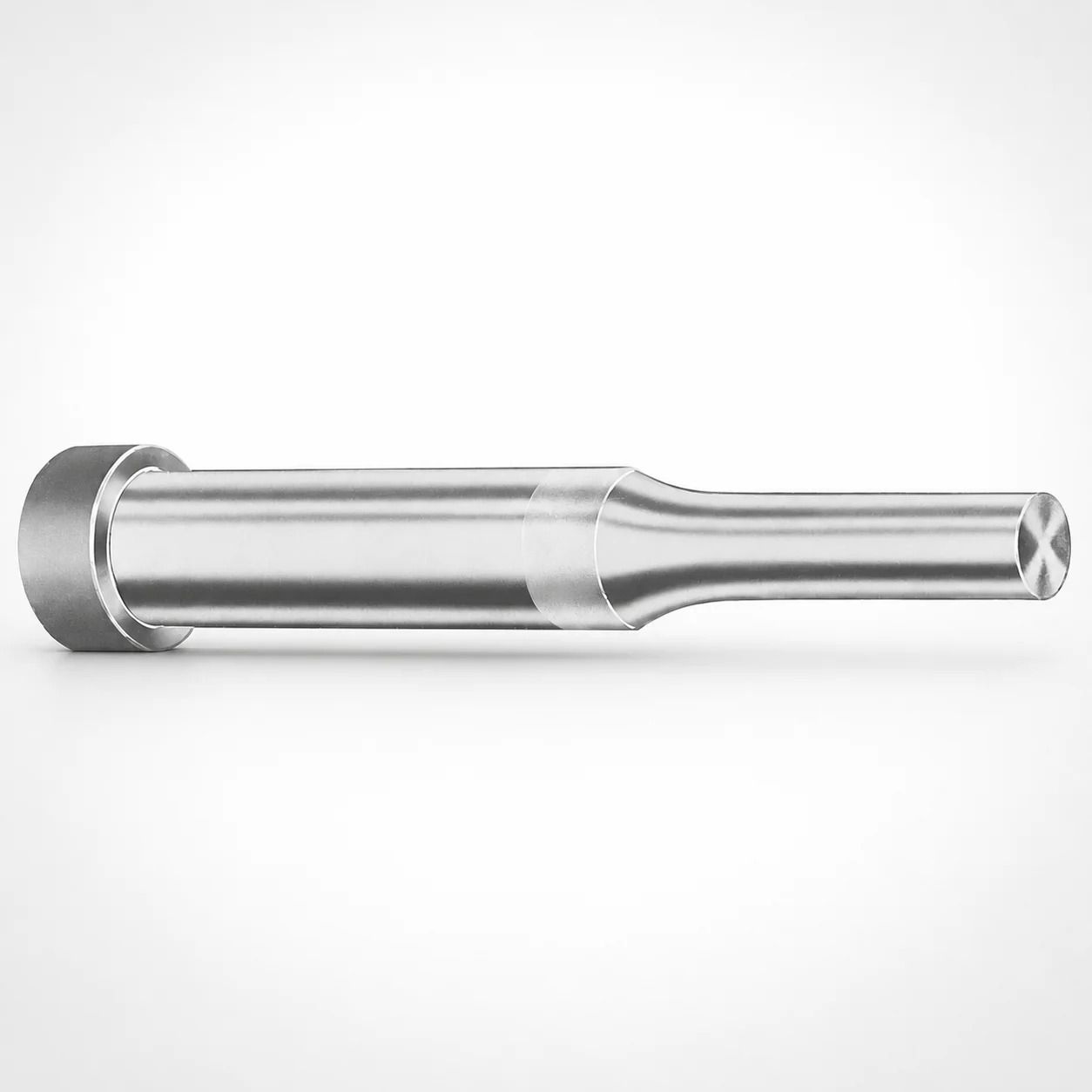
Regular Punches - Inch CRN Coating
Regular Punches - Inch CRN Coating are designed for dependable cutting and forming in tool and die applications, helping reduce wear on punch working surfaces while maintaining consistent punch geometry during production.
- CRN coating improves wear resistance and supports stable forming cycles
- Inch regular punch style supports die maintenance with predictable punch fit
- Multiple selectable tip shapes (X/R/K/O/H/L/J/N/V/Y/Z) for matching workpiece requirements
- Suitable for progressive dies and general press tooling where repeatable cutting is critical
Specifications
882 configurations available
| Tip shape | D (Shank dia.) (in) | Standard [S] Point Length B & L (Length) (coded inch) | Alternate [B] Point Length B & L (Length) (coded inch) | Alternate [C] Point Length B & L (Length) (coded inch) | Alternate [D] Point Length B & L (Length) (coded inch) | Alternate [E] Point Length B & L (Length) (coded inch) | P Dimension (in) | W Dimension (in) | R Dimension (in) |
|---|---|---|---|---|---|---|---|---|---|
| H | 12(0.1250") | - | 150 ~ 400 | - | - | - | 0.062 ~ 0.125 | 0.062 ~ 0.125 | - |
| H | 12(0.1250") | 150 ~ 400 | - | - | - | - | 0.062 ~ 0.125 | 0.062 ~ 0.125 | - |
| H | 18(0.1875") | - | 150 ~ 500 | - | - | - | 0.062 ~ 0.1875 | 0.062 ~ 0.1875 | - |
| H | 18(0.1875") | 150 ~ 500 | - | - | - | - | 0.062 ~ 0.1875 | 0.062 ~ 0.1875 | - |
| H | 25(0.2500") | - | 150 ~ 600 | - | - | - | 0.062 ~ 0.25 | 0.062 ~ 0.0929 | - |
| H | 25(0.2500") | - | 150 ~ 600 | - | - | - | 0.062 ~ 0.25 | 0.093 ~ 0.25 | - |
| H | 25(0.2500") | 150 ~ 600 | - | - | - | - | 0.062 ~ 0.25 | 0.062 ~ 0.0929 | - |
| H | 25(0.2500") | 150 ~ 600 | - | - | - | - | 0.062 ~ 0.25 | 0.093 ~ 0.25 | - |
| H | 31(0.3125") | - | 150 ~ 600 | - | - | - | 0.062 ~ 0.3125 | 0.062 ~ 0.1249 | - |
| H | 31(0.3125") | - | 150 ~ 600 | - | - | - | 0.062 ~ 0.3125 | 0.125 ~ 0.3125 | - |
| H | 31(0.3125") | - | - | 175 ~ 600 | - | - | 0.062 ~ 0.3125 | 0.062 ~ 0.1249 | - |
| H | 31(0.3125") | - | - | 175 ~ 600 | - | - | 0.062 ~ 0.3125 | 0.125 ~ 0.3125 | - |
| H | 31(0.3125") | 150 ~ 600 | - | - | - | - | 0.062 ~ 0.3125 | 0.062 ~ 0.1249 | - |
| H | 31(0.3125") | 150 ~ 600 | - | - | - | - | 0.062 ~ 0.3125 | 0.125 ~ 0.3125 | - |
| H | 37(0.3750") | - | 175 ~ 600 | - | - | - | 0.08 ~ 0.375 | 0.08 ~ 0.1869 | - |
| H | 37(0.3750") | - | 175 ~ 600 | - | - | - | 0.08 ~ 0.375 | 0.187 ~ 0.375 | - |
| H | 37(0.3750") | - | - | 175 ~ 600 | - | - | 0.08 ~ 0.375 | 0.08 ~ 0.1869 | - |
| H | 37(0.3750") | - | - | 175 ~ 600 | - | - | 0.08 ~ 0.375 | 0.187 ~ 0.375 | - |
| H | 37(0.3750") | - | - | - | 200 ~ 600 | - | 0.08 ~ 0.375 | 0.08 ~ 0.1869 | - |
| H | 37(0.3750") | - | - | - | 200 ~ 600 | - | 0.08 ~ 0.375 | 0.187 ~ 0.375 | - |
| H | 37(0.3750") | 175 ~ 600 | - | - | - | - | 0.08 ~ 0.375 | 0.08 ~ 0.1869 | - |
| H | 37(0.3750") | 175 ~ 600 | - | - | - | - | 0.08 ~ 0.375 | 0.187 ~ 0.375 | - |
| H | 43(0.4375") | - | - | 200 ~ 700 | - | - | 0.158 ~ 0.4374 | 0.158 ~ 0.1869 | - |
| H | 43(0.4375") | - | - | 200 ~ 700 | - | - | 0.158 ~ 0.4374 | 0.187 ~ 0.4374 | - |
| H | 43(0.4375") | - | - | - | 200 ~ 700 | - | 0.158 ~ 0.4374 | 0.158 ~ 0.1869 | - |
| H | 43(0.4375") | - | - | - | 200 ~ 700 | - | 0.158 ~ 0.4374 | 0.187 ~ 0.4374 | - |
| H | 43(0.4375") | 200 ~ 700 | - | - | - | - | 0.158 ~ 0.4374 | 0.158 ~ 0.1869 | - |
| H | 43(0.4375") | 200 ~ 700 | - | - | - | - | 0.158 ~ 0.4374 | 0.187 ~ 0.4374 | - |
| H | 50(0.5000") | - | - | 200 ~ 700 | - | - | 0.158 ~ 0.5 | 0.158 ~ 0.1869 | - |
| H | 50(0.5000") | - | - | 200 ~ 700 | - | - | 0.158 ~ 0.5 | 0.187 ~ 0.5 | - |
| H | 50(0.5000") | - | - | - | 200 ~ 700 | - | 0.158 ~ 0.5 | 0.158 ~ 0.1869 | - |
| H | 50(0.5000") | - | - | - | 200 ~ 700 | - | 0.158 ~ 0.5 | 0.187 ~ 0.5 | - |
| H | 50(0.5000") | 200 ~ 700 | - | - | - | - | 0.158 ~ 0.5 | 0.158 ~ 0.1869 | - |
| H | 50(0.5000") | 200 ~ 700 | - | - | - | - | 0.158 ~ 0.5 | 0.187 ~ 0.5 | - |
| H | 62(0.6250") | - | - | - | 225 ~ 700 | - | 0.235 ~ 0.625 | 0.25 ~ 0.625 | - |
| H | 62(0.6250") | - | - | - | 225 ~ 700 | - | 0.235 ~ 0.625 | 0.235 ~ 0.2499 | - |
| H | 62(0.6250") | - | - | - | - | 225 ~ 700 | 0.235 ~ 0.625 | 0.25 ~ 0.625 | - |
| H | 62(0.6250") | - | - | - | - | 225 ~ 700 | 0.235 ~ 0.625 | 0.235 ~ 0.2499 | - |
| H | 62(0.6250") | 225 ~ 700 | - | - | - | - | 0.235 ~ 0.625 | 0.25 ~ 0.625 | - |
| H | 62(0.6250") | 225 ~ 700 | - | - | - | - | 0.235 ~ 0.625 | 0.235 ~ 0.2499 | - |
| H | 75(0.7500") | - | - | - | 225 ~ 700 | - | 0.235 ~ 0.75 | 0.235 ~ 0.3119 | - |
| H | 75(0.7500") | - | - | - | 225 ~ 700 | - | 0.235 ~ 0.75 | 0.312 ~ 0.75 | - |
| H | 75(0.7500") | - | - | - | - | 225 ~ 700 | 0.235 ~ 0.75 | 0.235 ~ 0.3119 | - |
| H | 75(0.7500") | - | - | - | - | 225 ~ 700 | 0.235 ~ 0.75 | 0.312 ~ 0.75 | - |
| H | 75(0.7500") | 225 ~ 700 | - | - | - | - | 0.235 ~ 0.75 | 0.235 ~ 0.3119 | - |
| H | 75(0.7500") | 225 ~ 700 | - | - | - | - | 0.235 ~ 0.75 | 0.312 ~ 0.75 | - |
| H | 87(0.8750") | - | - | - | 225 ~ 700 | - | 0.235 ~ 0.875 | 0.235 ~ 0.3119 | - |
| H | 87(0.8750") | - | - | - | 225 ~ 700 | - | 0.235 ~ 0.875 | 0.312 ~ 0.875 | - |
| H | 87(0.8750") | - | - | - | - | 225 ~ 700 | 0.235 ~ 0.875 | 0.235 ~ 0.3119 | - |
| H | 87(0.8750") | - | - | - | - | 225 ~ 700 | 0.235 ~ 0.875 | 0.312 ~ 0.875 | - |
Product Guide
Application Scenarios+
Regular punches with CRN (carbonitride) coating are used in industrial press tooling for forming and trimming operations where tooling must hold geometry over long production runs. The CRN surface is suited to applications that experience sliding contact and edge wear, helping extend punch service life while keeping consistent cut quality.
In progressive die sets for automotive and industrial connectors, these punches support repeatable blanking and trimming cycles. The availability of multiple tip shapes (e.g., X/R/K/O/H/L/J/N/V/Y/Z) allows engineers to match shear geometry to part thickness and edge finish requirements, improving stability across high-volume cycles.
For general metal forming and gate/port trimming in housings, the inch regular punch style supports practical die maintenance with predictable punch fit. Shank diameter and length coding ranges (D 12–250 in; point length options up to 700 coded inches) enable selection for different cavity/core setups without repeated rework.
- CRN coating for controlled wear on working surfaces
- Multiple tip shapes to align with forming/trimming geometry
- Inch punch format for compatibility with standard tooling practices
Material & Process Details+
This variant is specified as a Regular Punch with inch CRN coating, meaning the primary technical differentiator is the coated working surface designed to improve wear performance at the punch edge and shear zone.
CRN (carbonitride) coating is commonly selected to increase wear resistance and support stable punch performance during repeated forming/trimming contact. In service, this typically improves edge durability, which can reduce dimensional drift from edge rounding compared with uncoated or lower-wear surfaces.
Because the input data does not provide the underlying steel grade, base hardness, or an explicit heat-treatment condition (e.g., through-hardening, quenched & tempered, nitriding), hardness and toughness trade-offs cannot be stated for this item specifically. For selection, engineers should confirm the base material and hardness with the punch drawing to ensure the coating and substrate form a suitable wear/toughness balance.
- Coating focus: CRN wear resistance on punch working surfaces
- Heat treatment: not specified in provided data—verify on request
- Material comparison: base grade varies by manufacturer build—confirm substrate vs. coated performance
Sizing & Selection Guide+
Use the provided specification ranges to match the punch to the die cavity/core opening and required working penetration. Start with shank diameter (D): select a value within 12–250 in so the punch fits the guide/bushing system used in your progressive die or press tool.
Next, choose the tip shape (H, J, K, L, N, O, R, V, X, Y, Z) to align with the shear profile and part edge geometry. The tip shape affects how the cutting edge engages the sheet/strip, which is critical for forming and trimming consistency.
Then select point length using the coded ranges for Standard [S] point length B & L (Length): 150–250. If you require longer reach, use alternate options such as [B] 150–400, 150–500, 150–600, or 175–600; and [C] 175–600 or 200–700, or [D]/[E] up to 225–700 and 250–700 respectively.
- Match D (12–250) to your guide/bushing bore and fit requirements
- Select length code to achieve required penetration without bottoming
- Choose tip shape to target the desired cut/forming geometry
Frequently Asked Questions
How do I select the correct punch shank diameter (D) range for a progressive die setup?+
Which tip shapes (H, J, K, L, N, O, R, V, X, Y, Z) should be chosen for trimming vs. forming?+
What point-length options are available for this inch CRN-coated regular punch series?+
Does the CRN coating choice affect hardness and toughness, and how should I verify it for tool life?+
How should P, W, and R dimensions be used during dimensional compatibility checks?+
Related Products






Need Custom Specifications?
Our engineering team can help with custom configurations, material selection, and volume pricing.