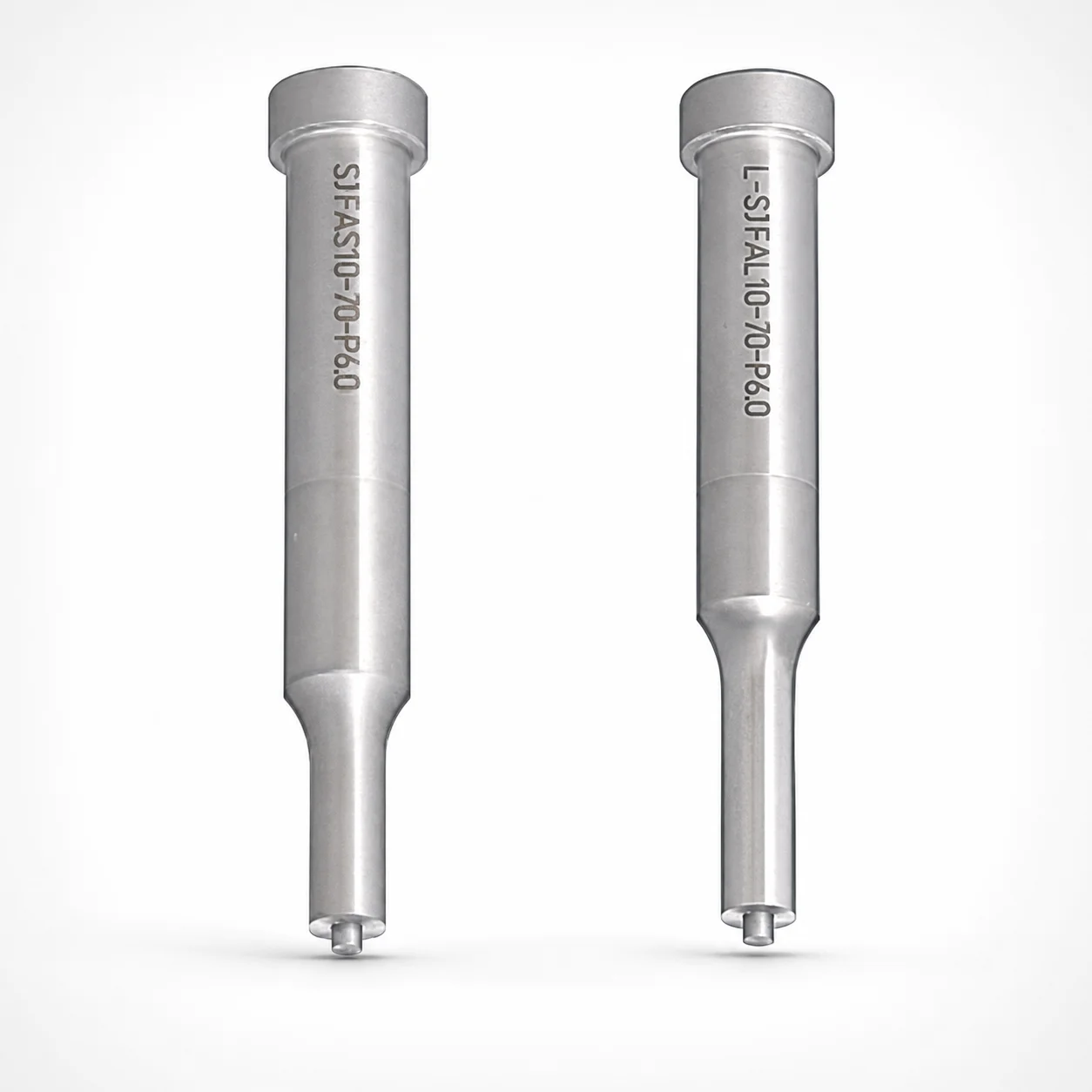
Jector Punches - Large Diameter Ejector Pins (Lapping) SKD11 (D2)
Jector Punches - Large Diameter Ejector Pins (Lapping) (SKD11 (D2) steel) deliver robust heavy-duty ejection performance, with an optional lapping surface to improve fit and working consistency. The single-stepped shank and large-diameter punch design support precise, repeatable results in demanding molds.
- Single-stepped shank with large-diameter jector pins for stable alignment
- Built from SKD11 (D2) steel with wear-resistant cutting performance
- Optional lapping surface helps maintain smooth contact during operation
- Suitable for high-demand die and mold applications requiring reliable punch life
Specifications
7922 configurations available
| Tip shape | Surface treatment | B (Tip length) | D (Shank diameter) (mm) | P (Tip dimension) (mm) | L (L dimension) (mm) | LC (Full length alteration) (mm) | LCT (Head thickness tolerance change + Total length alteration) (mm) | LMT (Head thickness tolerance change + Total length alteration) (mm) | PC (Tip dimension alteration) (mm) | R (Tip corner R) (mm) | W (Tip dimension) (mm) | WC (Tip dimension alteration) (mm) | type |
|---|---|---|---|---|---|---|---|---|---|---|---|---|---|
| Round | Lapping | L | 8 | 5 ~ 7.99 | 50 ~ 100 | - | - | - | - | - | - | - | - |
| Round | Lapping | L | 8 | - | 50 ~ 100 | - | - | - | 4.5 ~ 4.99 | - | - | - | - |
| Round | Lapping | L | 8 | 5 ~ 7.99 | - | 33 ~ 49.9 | - | - | - | - | - | - | - |
| Round | Lapping | L | 8 | - | - | 33 ~ 49.9 | - | - | 4.5 ~ 4.99 | - | - | - | - |
| Round | Lapping | L | 8 | 5 ~ 7.99 | - | 50.1 ~ 59.9 | - | - | - | - | - | - | - |
| Round | Lapping | L | 8 | - | - | 50.1 ~ 59.9 | - | - | 4.5 ~ 4.99 | - | - | - | - |
| Round | Lapping | L | 8 | 5 ~ 7.99 | - | 60.1 ~ 69.9 | - | - | - | - | - | - | - |
| Round | Lapping | L | 8 | - | - | 60.1 ~ 69.9 | - | - | 4.5 ~ 4.99 | - | - | - | - |
| Round | Lapping | L | 8 | 5 ~ 7.99 | - | 70.1 ~ 79.9 | - | - | - | - | - | - | - |
| Round | Lapping | L | 8 | - | - | 70.1 ~ 79.9 | - | - | 4.5 ~ 4.99 | - | - | - | - |
| Round | Lapping | L | 8 | 5 ~ 7.99 | - | 80.1 ~ 89.9 | - | - | - | - | - | - | - |
| Round | Lapping | L | 8 | - | - | 80.1 ~ 89.9 | - | - | 4.5 ~ 4.99 | - | - | - | - |
| Round | Lapping | L | 8 | 5 ~ 7.99 | - | 90.1 ~ 99.9 | - | - | - | - | - | - | - |
| Round | Lapping | L | 8 | - | - | 90.1 ~ 99.9 | - | - | 4.5 ~ 4.99 | - | - | - | - |
| Round | Lapping | L | 8 | 5 ~ 7.99 | - | - | 33 ~ 49.9 | - | - | - | - | - | - |
| Round | Lapping | L | 8 | - | - | - | 33 ~ 49.9 | - | 4.5 ~ 4.99 | - | - | - | - |
| Round | Lapping | L | 8 | 5 ~ 7.99 | - | - | 50.1 ~ 59.9 | - | - | - | - | - | - |
| Round | Lapping | L | 8 | - | - | - | 50.1 ~ 59.9 | - | 4.5 ~ 4.99 | - | - | - | - |
| Round | Lapping | L | 8 | 5 ~ 7.99 | - | - | 60.1 ~ 69.9 | - | - | - | - | - | - |
| Round | Lapping | L | 8 | - | - | - | 60.1 ~ 69.9 | - | 4.5 ~ 4.99 | - | - | - | - |
| Round | Lapping | L | 8 | 5 ~ 7.99 | - | - | 70.1 ~ 79.9 | - | - | - | - | - | - |
| Round | Lapping | L | 8 | - | - | - | 70.1 ~ 79.9 | - | 4.5 ~ 4.99 | - | - | - | - |
| Round | Lapping | L | 8 | 5 ~ 7.99 | - | - | 80.1 ~ 89.9 | - | - | - | - | - | - |
| Round | Lapping | L | 8 | - | - | - | 80.1 ~ 89.9 | - | 4.5 ~ 4.99 | - | - | - | - |
| Round | Lapping | L | 8 | 5 ~ 7.99 | - | - | 90.1 ~ 99.9 | - | - | - | - | - | - |
| Round | Lapping | L | 8 | - | - | - | 90.1 ~ 99.9 | - | 4.5 ~ 4.99 | - | - | - | - |
| Round | Lapping | L | 8 | 5 ~ 7.99 | - | - | - | 33 ~ 49.9 | - | - | - | - | - |
| Round | Lapping | L | 8 | - | - | - | - | 33 ~ 49.9 | 4.5 ~ 4.99 | - | - | - | - |
| Round | Lapping | L | 8 | 5 ~ 7.99 | - | - | - | 50.1 ~ 59.9 | - | - | - | - | - |
| Round | Lapping | L | 8 | - | - | - | - | 50.1 ~ 59.9 | 4.5 ~ 4.99 | - | - | - | - |
| Round | Lapping | L | 8 | 5 ~ 7.99 | - | - | - | 60.1 ~ 69.9 | - | - | - | - | - |
| Round | Lapping | L | 8 | - | - | - | - | 60.1 ~ 69.9 | 4.5 ~ 4.99 | - | - | - | - |
| Round | Lapping | L | 8 | 5 ~ 7.99 | - | - | - | 70.1 ~ 79.9 | - | - | - | - | - |
| Round | Lapping | L | 8 | - | - | - | - | 70.1 ~ 79.9 | 4.5 ~ 4.99 | - | - | - | - |
| Round | Lapping | L | 8 | 5 ~ 7.99 | - | - | - | 80.1 ~ 89.9 | - | - | - | - | - |
| Round | Lapping | L | 8 | - | - | - | - | 80.1 ~ 89.9 | 4.5 ~ 4.99 | - | - | - | - |
| Round | Lapping | L | 8 | 5 ~ 7.99 | - | - | - | 90.1 ~ 99.9 | - | - | - | - | - |
| Round | Lapping | L | 8 | - | - | - | - | 90.1 ~ 99.9 | 4.5 ~ 4.99 | - | - | - | - |
| Round | Lapping | L | 10 | 5 ~ 9.99 | 50 ~ 100 | - | - | - | - | - | - | - | - |
| Round | Lapping | L | 10 | - | 50 ~ 100 | - | - | - | 4.5 ~ 4.99 | - | - | - | - |
| Round | Lapping | L | 10 | 5 ~ 9.99 | - | 33 ~ 49.9 | - | - | - | - | - | - | - |
| Round | Lapping | L | 10 | - | - | 33 ~ 49.9 | - | - | 4.5 ~ 4.99 | - | - | - | - |
| Round | Lapping | L | 10 | 5 ~ 9.99 | - | 50.1 ~ 59.9 | - | - | - | - | - | - | - |
| Round | Lapping | L | 10 | - | - | 50.1 ~ 59.9 | - | - | 4.5 ~ 4.99 | - | - | - | - |
| Round | Lapping | L | 10 | 5 ~ 9.99 | - | 60.1 ~ 69.9 | - | - | - | - | - | - | - |
| Round | Lapping | L | 10 | - | - | 60.1 ~ 69.9 | - | - | 4.5 ~ 4.99 | - | - | - | - |
| Round | Lapping | L | 10 | 5 ~ 9.99 | - | 70.1 ~ 79.9 | - | - | - | - | - | - | - |
| Round | Lapping | L | 10 | - | - | 70.1 ~ 79.9 | - | - | 4.5 ~ 4.99 | - | - | - | - |
| Round | Lapping | L | 10 | 5 ~ 9.99 | - | 80.1 ~ 89.9 | - | - | - | - | - | - | - |
| Round | Lapping | L | 10 | - | - | 80.1 ~ 89.9 | - | - | 4.5 ~ 4.99 | - | - | - | - |
Product Guide
Application Scenarios+
Large-diameter jector punches are used in injection mold tooling where high ejection force must be transferred with excellent alignment and repeatability. In automotive connector and harness-molding applications, the single-stepped shank and the available shank diameters (8 to 25 mm) help resist deflection while maintaining stable contact during part release.
For consumer electronics and durable appliance housings, the optional lapping surface supports smoother, more consistent wear contact, reducing the risk of uneven punch-to-bushing behavior over repeated cycles. This is especially relevant when tight working clearance and consistent ejection travel are required.
In demanding die and mold builds—such as those producing thick-walled parts or high-friction surfaces—choosing the SKD11 (D2) steel variant supports heavy-duty punch life while still enabling a controlled fit strategy using the available tip geometries (round, rectangle, oblong, and flatted/radius forms).
- Automotive connector molds: alignment under high ejection load via large shank diameter and stepped design
- Electronics appliance housings: lapped option for smoother contact and stable working performance
- High-demand die/mold applications: SKD11 (D2) wear-focused punching
Material & Process Details+
This punch is specified in SKD11 (D2) steel, a wear-focused tool steel commonly selected for punch components that experience repeated sliding/contact during ejection. While the product data provides the grade designation (SKD11 (D2)), it does not specify the exact heat-treatment target or hardness value; therefore, selection should follow the maker’s documented treatment for this grade within your mold build spec.
In general tool-steel practice for D2-family grades, hardness and wear resistance are achieved through quenching and tempering to balance toughness against abrasion. Expect strong resistance to surface wear at the tip, with the typical trade-off that higher hardness can reduce toughness—making design of support and guidance important for long-cycle molds.
- SKD11 (D2): wear-resistant heavy-duty punch performance for ejection applications
- Lapping surface option: improves contact consistency at the working face (when selected)
Sizing & Selection Guide+
Start sizing by matching the shank diameter D (8, 10, 13, 16, 20, 25 mm) to the corresponding guide/punch support design in your mold (e.g., ejector plate support or bushings). Larger D values improve stiffness for high-load ejection, but must align with your available support bore.
Select the tip geometry (Round, Rectangle, Oblong, Double Flatted Round, Radius Rectangle) and then choose the tip dimensions: P (5 ~ 33 mm) and tip W (5 ~ 10 mm) (as applicable to the selected tip form). Use the required corner radius R (0.15 ~ up to 12.48 mm depending on variant range) to avoid excessive stress concentration on the part-release interface.
Verify overall length using L (50 ~ 100 mm, or 60 ~ 100 mm by option) and the full-length alteration LC (33 ~ 90.1 mm) to ensure correct engagement through the moving components. Consider tolerances carefully where length alteration values like LCT/LMT (33 ~ 90.1 mm) are specified, as they represent tolerance-related changes to total length.
- Match D to support/guide bore
- Match tip shape + P/W/R to part-release geometry
- Confirm L and LC (and LCT/LMT) to achieve correct stroke and clearance
Frequently Asked Questions
How do I choose between lapping and non-lapping surface treatment for SKD11 (D2) jector punches?+
What shank diameters (D) are available for these large-diameter jector punches, and how does that impact stiffness?+
Which tip geometries are offered, and how should I map them to P/W/R dimensions in the specification?+
How do L, LC, and LCT/LMT dimensions relate when ensuring the correct overall length?+
What are PC and WC, and when do I need to pay attention to these alteration values?+
Related Products






Need Custom Specifications?
Our engineering team can help with custom configurations, material selection, and volume pricing.