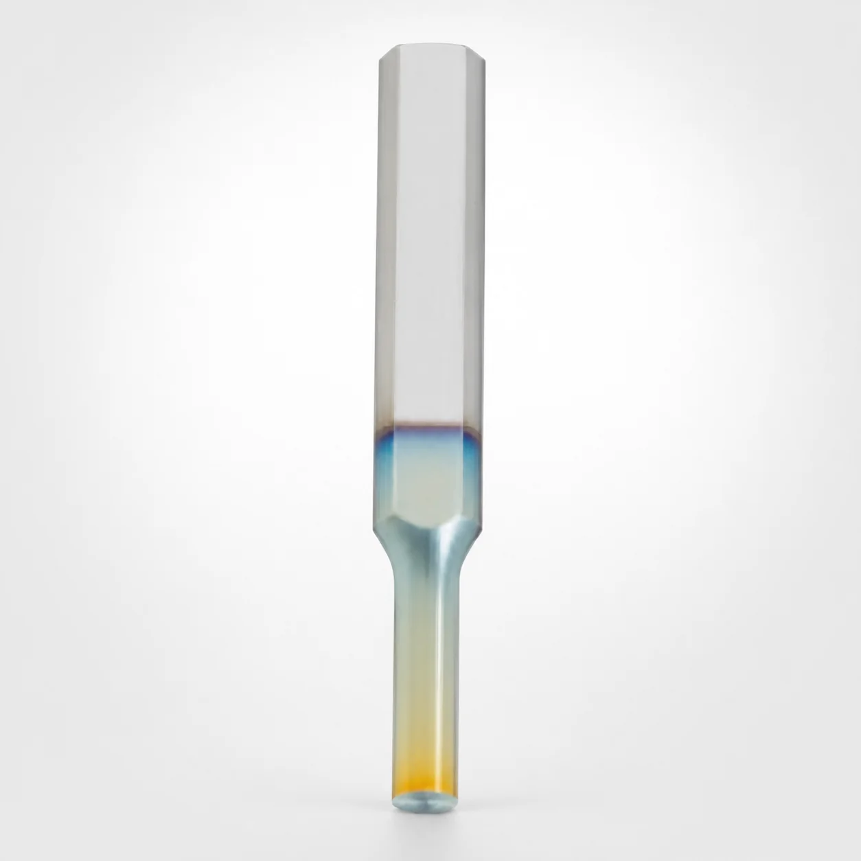
Key Flat Shank Tapped Punches - DLC Coating
Key Flat Shank Tapped Punches - DLC Coating (SKH40-equivalent powdered high-speed steel) are designed for stable guiding and reliable pull-through during repeated press cycles. The key flat tap mounting helps maintain alignment for consistent forming results.
- Single-stepped shank with key flat tap geometry for positive anti-rotation positioning
- DLC (XCD) coating improves surface wear resistance for longer punch life
- Machined assembly fit supports controlled shank diameter +0.005/0 for accurate tool engagement
- Tapped standard type suited for die sets and progressive tooling where repeatable punch location is critical
Specifications
1128 configurations available
| Tip shape | Surface treatment | B (Tip length) | D (Shank diameter) (mm) | P (Tip dimension) (mm) | L (L dimension) (mm) | LC (Full length alteration) (mm) | PC (Tip dimension alteration) (mm) | R (Tip corner R) (mm) | W (Tip dimension) (mm) | WC (Tip dimension alteration) (mm) | type |
|---|---|---|---|---|---|---|---|---|---|---|---|
| Round | DLC (XCD) Coating | L | 6 | 2 ~ 3.8 | 50 ~ 80 | - | - | - | - | - | - |
| Round | DLC (XCD) Coating | L | 6 | - | 50 ~ 80 | - | 1 ~ 1.99 | - | - | - | - |
| Round | DLC (XCD) Coating | L | 6 | 2 ~ 3.8 | - | 27 ~ 79.9 | - | - | - | - | - |
| Round | DLC (XCD) Coating | L | 6 | - | - | 27 ~ 79.9 | 1 ~ 1.99 | - | - | - | - |
| Round | DLC (XCD) Coating | L | 8 | 3 ~ 5.8 | 50 ~ 100 | - | - | - | - | - | - |
| Round | DLC (XCD) Coating | L | 8 | - | 50 ~ 100 | - | 1.5 ~ 2.99 | - | - | - | - |
| Round | DLC (XCD) Coating | L | 8 | 3 ~ 5.8 | - | 27 ~ 99.9 | - | - | - | - | - |
| Round | DLC (XCD) Coating | L | 8 | - | - | 27 ~ 99.9 | 1.5 ~ 2.99 | - | - | - | - |
| Round | DLC (XCD) Coating | L | 10 | 3 ~ 7.8 | 50 ~ 100 | - | - | - | - | - | - |
| Round | DLC (XCD) Coating | L | 10 | - | 50 ~ 100 | - | 1.5 ~ 2.99 | - | - | - | - |
| Round | DLC (XCD) Coating | L | 10 | 3 ~ 7.8 | - | 27 ~ 99.9 | - | - | - | - | - |
| Round | DLC (XCD) Coating | L | 10 | - | - | 27 ~ 99.9 | 1.5 ~ 2.99 | - | - | - | - |
| Round | DLC (XCD) Coating | L | 13 | 6 ~ 10.8 | 50 ~ 100 | - | - | - | - | - | - |
| Round | DLC (XCD) Coating | L | 13 | - | 50 ~ 100 | - | 3 ~ 5.99 | - | - | - | - |
| Round | DLC (XCD) Coating | L | 13 | 6 ~ 10.8 | - | 27 ~ 99.9 | - | - | - | - | - |
| Round | DLC (XCD) Coating | L | 13 | - | - | 27 ~ 99.9 | 3 ~ 5.99 | - | - | - | - |
| Round | DLC (XCD) Coating | L | 16 | 10 ~ 13.8 | 60 ~ 100 | - | - | - | - | - | - |
| Round | DLC (XCD) Coating | L | 16 | - | 60 ~ 100 | - | 5 ~ 9.99 | - | - | - | - |
| Round | DLC (XCD) Coating | L | 16 | 10 ~ 13.8 | - | 27 ~ 99.9 | - | - | - | - | - |
| Round | DLC (XCD) Coating | L | 16 | - | - | 27 ~ 99.9 | 5 ~ 9.99 | - | - | - | - |
| Round | DLC (XCD) Coating | L | 20 | 13 ~ 17.8 | 60 ~ 100 | - | - | - | - | - | - |
| Round | DLC (XCD) Coating | L | 20 | - | 60 ~ 100 | - | 6.5 ~ 12.99 | - | - | - | - |
| Round | DLC (XCD) Coating | L | 20 | 13 ~ 17.8 | - | 27 ~ 99.9 | - | - | - | - | - |
| Round | DLC (XCD) Coating | L | 20 | - | - | 27 ~ 99.9 | 6.5 ~ 12.99 | - | - | - | - |
| Round | DLC (XCD) Coating | L | 25 | 18 ~ 22.8 | 60 ~ 100 | - | - | - | - | - | - |
| Round | DLC (XCD) Coating | L | 25 | - | 60 ~ 100 | - | 9 ~ 17.99 | - | - | - | - |
| Round | DLC (XCD) Coating | L | 25 | 18 ~ 22.8 | - | 27 ~ 99.9 | - | - | - | - | - |
| Round | DLC (XCD) Coating | L | 25 | - | - | 27 ~ 99.9 | 9 ~ 17.99 | - | - | - | - |
| Round | DLC (XCD) Coating | S | 6 | 2 ~ 3.8 | 40 ~ 80 | - | - | - | - | - | - |
| Round | DLC (XCD) Coating | S | 6 | - | 40 ~ 80 | - | 1 ~ 1.99 | - | - | - | - |
| Round | DLC (XCD) Coating | S | 6 | 2 ~ 3.8 | - | 27 ~ 79.9 | - | - | - | - | - |
| Round | DLC (XCD) Coating | S | 6 | - | - | 27 ~ 79.9 | 1 ~ 1.99 | - | - | - | - |
| Round | DLC (XCD) Coating | S | 8 | 3 ~ 5.8 | 40 ~ 100 | - | - | - | - | - | - |
| Round | DLC (XCD) Coating | S | 8 | - | 40 ~ 100 | - | 1.5 ~ 2.99 | - | - | - | - |
| Round | DLC (XCD) Coating | S | 8 | 3 ~ 5.8 | - | 27 ~ 99.9 | - | - | - | - | - |
| Round | DLC (XCD) Coating | S | 8 | - | - | 27 ~ 99.9 | 1.5 ~ 2.99 | - | - | - | - |
| Round | DLC (XCD) Coating | S | 10 | 3 ~ 7.8 | 40 ~ 100 | - | - | - | - | - | - |
| Round | DLC (XCD) Coating | S | 10 | - | 40 ~ 100 | - | 1.5 ~ 2.99 | - | - | - | - |
| Round | DLC (XCD) Coating | S | 10 | 3 ~ 7.8 | - | 27 ~ 99.9 | - | - | - | - | - |
| Round | DLC (XCD) Coating | S | 10 | - | - | 27 ~ 99.9 | 1.5 ~ 2.99 | - | - | - | - |
| Round | DLC (XCD) Coating | S | 13 | 6 ~ 10.8 | 40 ~ 100 | - | - | - | - | - | - |
| Round | DLC (XCD) Coating | S | 13 | - | 40 ~ 100 | - | 3 ~ 5.99 | - | - | - | - |
| Round | DLC (XCD) Coating | S | 13 | 6 ~ 10.8 | - | 27 ~ 99.9 | - | - | - | - | - |
| Round | DLC (XCD) Coating | S | 13 | - | - | 27 ~ 99.9 | 3 ~ 5.99 | - | - | - | - |
| Round | DLC (XCD) Coating | S | 16 | 10 ~ 13.8 | 40 ~ 100 | - | - | - | - | - | - |
| Round | DLC (XCD) Coating | S | 16 | - | 40 ~ 100 | - | 5 ~ 9.99 | - | - | - | - |
| Round | DLC (XCD) Coating | S | 16 | 10 ~ 13.8 | - | 27 ~ 99.9 | - | - | - | - | - |
| Round | DLC (XCD) Coating | S | 16 | - | - | 27 ~ 99.9 | 5 ~ 9.99 | - | - | - | - |
| Round | DLC (XCD) Coating | S | 20 | 13 ~ 17.8 | 40 ~ 100 | - | - | - | - | - | - |
| Round | DLC (XCD) Coating | S | 20 | - | 40 ~ 100 | - | 6.5 ~ 12.99 | - | - | - | - |
Product Guide
Application Scenarios+
Key flat shank tapped punches with DLC coating are used as fixed location punches in injection press and die tooling where repeatable part geometry depends on stable punch guidance. The key flat shank tap mounting provides positive anti-rotation positioning, helping maintain punch attitude through repeated cycles.
- Automotive connector and insert tooling: Suitable for forming and punching features in close-tolerance inserts because the DLC (XCD) surface treatment improves wear resistance during high-cycle press operations.
- Electronics housings and snap-feature dies: Works well in progressive or multi-station die sets where the punch must return to the same location to preserve critical critical dimensions.
- General precision progressive tooling: The DLC variant is suited when longer punch life is needed under abrasive contact, while the keyed flat shank helps prevent rotational drift in the cavity/core interface.
Select this variant when your tooling requires controlled engagement and positioning stability in close-tolerance work.
Material & Process Details+
This punch uses an SKH40-equivalent powdered high-speed steel substrate. Powder metallurgy processing refines carbides and supports consistent wear behavior under cyclic cutting and punching loads.
- DLC (XCD) coating: Deposited to enhance surface hardness and reduce adhesive/abrasive wear during repeated punch cycles.
- DLC + WPC (optional): Adds an additional wear-performance layer compared with DLC alone, targeting improved durability in more aggressive contact conditions.
- Heat treatment state: Provided as a hardened high-speed steel base suitable for precision punching applications; final performance depends on the supplier’s hardening and temper process for this steel grade.
In practice, increasing hardness improves wear resistance but can reduce toughness if over-hardened; the HSS family balance is chosen to maintain reasonable toughness for punch-through and forming operations.
Sizing & Selection Guide+
To select the correct keyed flat shank tapped punch, start by matching the shank diameter (D) to the guide bore and alignment features in your die set. The specified range is D = 6 ~ 25 mm, which must fit the corresponding holder/locating interface without clearance that could allow rotational or lateral movement.
- Choose the tip shape (Round, Rectangle, Oblong, Double Flatted Round, Radius Rectangle) to match the cavity/core feature you need to form.
- Select the tip dimension set: P = 1.5 ~ 18 mm and W = 1.5 ~ 6 mm (with corresponding dimensional options). For corner geometry, use R = 0.15 mm.
- Confirm overall geometry: available L ranges include 50–80, 50–100, 60–100, 40–80, 40–100 mm, and the full-length alteration LC = 27–99.9 mm (variant-dependent). Tip alteration PC = 1 ~ 9 mm and WC = 1 ~ 3 mm should align to your sharpening allowance and working length.
Note the assembly fit guidance stated for this series: the shank diameter is controlled at +0.005/0, so design the mounting hole/guide for a tight, repeatable engagement to preserve punch alignment.
Frequently Asked Questions
Which DLC surface option should I choose: DLC (XCD) or DLC + WPC?+
DLC (XCD) is the base option for improved surface wear resistance during repeated press cycles. If your application has more abrasive or higher-friction contact, the DLC + WPC variant is selected to add extra wear-performance capability compared with DLC alone.
How do I prevent punch rotation in a die set using this keyed flat shank design?+
This series uses a key flat tap geometry on the shank to provide positive anti-rotation positioning. When you match the D = 6 ~ 25 mm shank diameter to the corresponding holder/interface and maintain the tight fit (+0.005/0), rotational drift is minimized during repeated cycles.
What dimensional parameters are most critical for matching the punch tip to my cavity/core feature?+
The critical tip parameters are tip shape plus the tip dimensions P = 1.5 ~ 18 mm and W = 1.5 ~ 6 mm, along with the corner radius R = 0.15 mm. Also verify the working length via L and the alteration ranges LC = 27–99.9 mm (variant-dependent) and PC = 1 ~ 9 mm.
How should I select the punch length (L and LC) for correct working stroke without interfering with the die set?+
Choose L from the available ranges (40–80, 40–100, 50–80, 50–100, 60–100 mm) based on your press stroke and die stack-up. Then align LC (full-length alteration) within the series options (27–99.9 mm) and apply PC/WC alterations if you need dimensional fine-tuning for the tip or working height.
Is the shank fit tolerance already controlled, and what clearance should I design for?+
The content specifies an assembly fit guidance for shank diameter: +0.005/0. That indicates the shank is controlled to a tight engagement condition relative to the mating interface, so your guide/holder hole should be designed to avoid excessive clearance that could reduce alignment stability.
Related Products






Need Custom Specifications?
Our engineering team can help with custom configurations, material selection, and volume pricing.