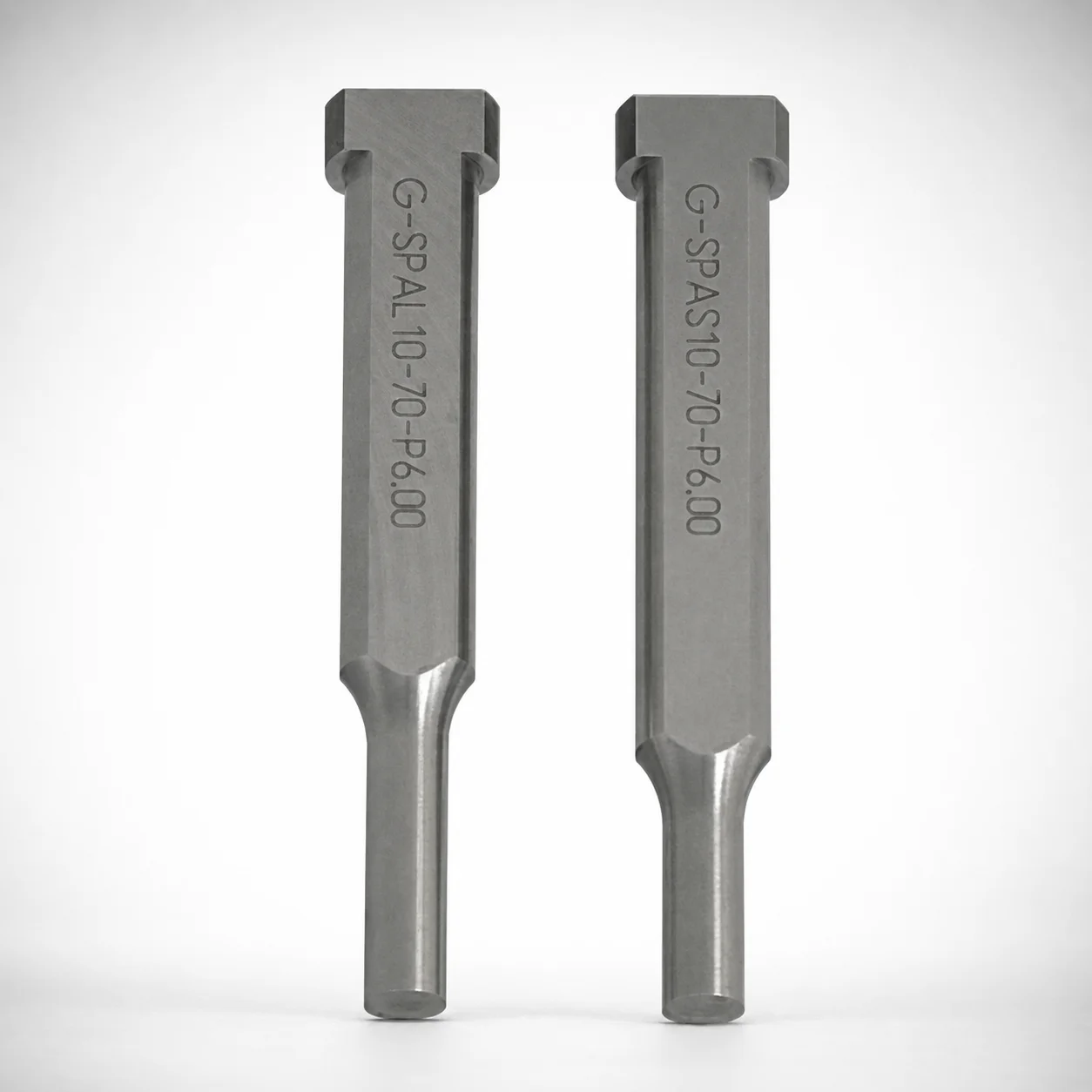
TiCN Coated Key Flat Shank Shoulder Punches
Key Flat Shank Shoulder Punches (TiCN coated option) are built for heavy-load punch applications where stable seating and reliable cutting performance are required. The key flat shank design improves guidance and reduces rotation during operation.
- Key flat shank with single-stepped shoulder for controlled punch guidance
- TiCN (XCN) coating option helps enhance wear resistance
- Compatible with multiple tip shapes for matching die and forming geometry
- Used in progressive dies and precision punching operations requiring repeatable results
Specifications
7324 configurations available
| Tip shape | Material | Surface treatment | B (Tip length) | D (Shank diameter) (mm) | P (Tip dimension) (mm) | L (L dimension) (mm) | LC (Full length alteration) (mm) | LCT (Head thickness tolerance change + Total length alteration) (mm) | LMT (Head thickness tolerance change + Total length alteration) (mm) | PC (Tip dimension alteration) (mm) | R (Tip corner R) (mm) | W (Tip dimension) (mm) | WC (Tip dimension alteration) (mm) | type |
|---|---|---|---|---|---|---|---|---|---|---|---|---|---|---|
| Round | SKH40 Equivalent (Powdered High-Speed Steel) | None | L | 3 | 1 ~ 1.8 | 40 ~ 100 | - | - | - | - | - | - | - | - |
| Round | SKH40 Equivalent (Powdered High-Speed Steel) | None | L | 3 | - | 40 ~ 100 | - | - | - | 0.5 ~ 0.99 | - | - | - | - |
| Round | SKH40 Equivalent (Powdered High-Speed Steel) | None | L | 3 | 1 ~ 1.8 | - | 27 ~ 99.9 | - | - | - | - | - | - | - |
| Round | SKH40 Equivalent (Powdered High-Speed Steel) | None | L | 3 | - | - | 27 ~ 99.9 | - | - | 0.5 ~ 0.99 | - | - | - | - |
| Round | SKH40 Equivalent (Powdered High-Speed Steel) | None | L | 3 | 1 ~ 1.8 | - | - | 27 ~ 99.9 | - | - | - | - | - | - |
| Round | SKH40 Equivalent (Powdered High-Speed Steel) | None | L | 3 | - | - | - | 27 ~ 99.9 | - | 0.5 ~ 0.99 | - | - | - | - |
| Round | SKH40 Equivalent (Powdered High-Speed Steel) | None | L | 3 | 1 ~ 1.8 | - | - | - | 27 ~ 99.9 | - | - | - | - | - |
| Round | SKH40 Equivalent (Powdered High-Speed Steel) | None | L | 3 | - | - | - | - | 27 ~ 99.9 | 0.5 ~ 0.99 | - | - | - | - |
| Round | SKH40 Equivalent (Powdered High-Speed Steel) | None | L | 4 | 1 ~ 2.8 | 50 ~ 100 | - | - | - | - | - | - | - | - |
| Round | SKH40 Equivalent (Powdered High-Speed Steel) | None | L | 4 | - | 50 ~ 100 | - | - | - | 0.5 ~ 0.99 | - | - | - | - |
| Round | SKH40 Equivalent (Powdered High-Speed Steel) | None | L | 4 | 1 ~ 2.8 | - | 27 ~ 99.9 | - | - | - | - | - | - | - |
| Round | SKH40 Equivalent (Powdered High-Speed Steel) | None | L | 4 | - | - | 27 ~ 99.9 | - | - | 0.5 ~ 0.99 | - | - | - | - |
| Round | SKH40 Equivalent (Powdered High-Speed Steel) | None | L | 4 | 1 ~ 2.8 | - | - | 27 ~ 99.9 | - | - | - | - | - | - |
| Round | SKH40 Equivalent (Powdered High-Speed Steel) | None | L | 4 | - | - | - | 27 ~ 99.9 | - | 0.5 ~ 0.99 | - | - | - | - |
| Round | SKH40 Equivalent (Powdered High-Speed Steel) | None | L | 4 | 1 ~ 2.8 | - | - | - | 27 ~ 99.9 | - | - | - | - | - |
| Round | SKH40 Equivalent (Powdered High-Speed Steel) | None | L | 4 | - | - | - | - | 27 ~ 99.9 | 0.5 ~ 0.99 | - | - | - | - |
| Round | SKH40 Equivalent (Powdered High-Speed Steel) | None | L | 5 | 2 ~ 3.8 | 50 ~ 100 | - | - | - | - | - | - | - | - |
| Round | SKH40 Equivalent (Powdered High-Speed Steel) | None | L | 5 | - | 50 ~ 100 | - | - | - | 1 ~ 1.99 | - | - | - | - |
| Round | SKH40 Equivalent (Powdered High-Speed Steel) | None | L | 5 | 2 ~ 3.8 | - | 27 ~ 99.9 | - | - | - | - | - | - | - |
| Round | SKH40 Equivalent (Powdered High-Speed Steel) | None | L | 5 | - | - | 27 ~ 99.9 | - | - | 1 ~ 1.99 | - | - | - | - |
| Round | SKH40 Equivalent (Powdered High-Speed Steel) | None | L | 5 | 2 ~ 3.8 | - | - | 27 ~ 99.9 | - | - | - | - | - | - |
| Round | SKH40 Equivalent (Powdered High-Speed Steel) | None | L | 5 | - | - | - | 27 ~ 99.9 | - | 1 ~ 1.99 | - | - | - | - |
| Round | SKH40 Equivalent (Powdered High-Speed Steel) | None | L | 5 | 2 ~ 3.8 | - | - | - | 27 ~ 99.9 | - | - | - | - | - |
| Round | SKH40 Equivalent (Powdered High-Speed Steel) | None | L | 5 | - | - | - | - | 27 ~ 99.9 | 1 ~ 1.99 | - | - | - | - |
| Round | SKH40 Equivalent (Powdered High-Speed Steel) | None | L | 6 | 2 ~ 4.8 | 50 ~ 100 | - | - | - | - | - | - | - | - |
| Round | SKH40 Equivalent (Powdered High-Speed Steel) | None | L | 6 | - | 50 ~ 100 | - | - | - | 1 ~ 1.99 | - | - | - | - |
| Round | SKH40 Equivalent (Powdered High-Speed Steel) | None | L | 6 | 2 ~ 4.8 | - | 27 ~ 99.9 | - | - | - | - | - | - | - |
| Round | SKH40 Equivalent (Powdered High-Speed Steel) | None | L | 6 | - | - | 27 ~ 99.9 | - | - | 1 ~ 1.99 | - | - | - | - |
| Round | SKH40 Equivalent (Powdered High-Speed Steel) | None | L | 6 | 2 ~ 4.8 | - | - | 27 ~ 99.9 | - | - | - | - | - | - |
| Round | SKH40 Equivalent (Powdered High-Speed Steel) | None | L | 6 | - | - | - | 27 ~ 99.9 | - | 1 ~ 1.99 | - | - | - | - |
| Round | SKH40 Equivalent (Powdered High-Speed Steel) | None | L | 6 | 2 ~ 4.8 | - | - | - | 27 ~ 99.9 | - | - | - | - | - |
| Round | SKH40 Equivalent (Powdered High-Speed Steel) | None | L | 6 | - | - | - | - | 27 ~ 99.9 | 1 ~ 1.99 | - | - | - | - |
| Round | SKH40 Equivalent (Powdered High-Speed Steel) | None | L | 8 | 3 ~ 5.8 | 50 ~ 100 | - | - | - | - | - | - | - | - |
| Round | SKH40 Equivalent (Powdered High-Speed Steel) | None | L | 8 | - | 50 ~ 100 | - | - | - | 1.5 ~ 2.99 | - | - | - | - |
| Round | SKH40 Equivalent (Powdered High-Speed Steel) | None | L | 8 | 3 ~ 5.8 | - | 27 ~ 99.9 | - | - | - | - | - | - | - |
| Round | SKH40 Equivalent (Powdered High-Speed Steel) | None | L | 8 | - | - | 27 ~ 99.9 | - | - | 1.5 ~ 2.99 | - | - | - | - |
| Round | SKH40 Equivalent (Powdered High-Speed Steel) | None | L | 8 | 3 ~ 5.8 | - | - | 27 ~ 99.9 | - | - | - | - | - | - |
| Round | SKH40 Equivalent (Powdered High-Speed Steel) | None | L | 8 | - | - | - | 27 ~ 99.9 | - | 1.5 ~ 2.99 | - | - | - | - |
| Round | SKH40 Equivalent (Powdered High-Speed Steel) | None | L | 8 | 3 ~ 5.8 | - | - | - | 27 ~ 99.9 | - | - | - | - | - |
| Round | SKH40 Equivalent (Powdered High-Speed Steel) | None | L | 8 | - | - | - | - | 27 ~ 99.9 | 1.5 ~ 2.99 | - | - | - | - |
| Round | SKH40 Equivalent (Powdered High-Speed Steel) | None | L | 10 | 3 ~ 7.8 | 50 ~ 100 | - | - | - | - | - | - | - | - |
| Round | SKH40 Equivalent (Powdered High-Speed Steel) | None | L | 10 | - | 50 ~ 100 | - | - | - | 1.5 ~ 2.99 | - | - | - | - |
| Round | SKH40 Equivalent (Powdered High-Speed Steel) | None | L | 10 | 3 ~ 7.8 | - | 27 ~ 99.9 | - | - | - | - | - | - | - |
| Round | SKH40 Equivalent (Powdered High-Speed Steel) | None | L | 10 | - | - | 27 ~ 99.9 | - | - | 1.5 ~ 2.99 | - | - | - | - |
| Round | SKH40 Equivalent (Powdered High-Speed Steel) | None | L | 10 | 3 ~ 7.8 | - | - | 27 ~ 99.9 | - | - | - | - | - | - |
| Round | SKH40 Equivalent (Powdered High-Speed Steel) | None | L | 10 | - | - | - | 27 ~ 99.9 | - | 1.5 ~ 2.99 | - | - | - | - |
| Round | SKH40 Equivalent (Powdered High-Speed Steel) | None | L | 10 | 3 ~ 7.8 | - | - | - | 27 ~ 99.9 | - | - | - | - | - |
| Round | SKH40 Equivalent (Powdered High-Speed Steel) | None | L | 10 | - | - | - | - | 27 ~ 99.9 | 1.5 ~ 2.99 | - | - | - | - |
| Round | SKH40 Equivalent (Powdered High-Speed Steel) | None | L | 13 | 6 ~ 10.8 | 50 ~ 100 | - | - | - | - | - | - | - | - |
| Round | SKH40 Equivalent (Powdered High-Speed Steel) | None | L | 13 | - | 50 ~ 100 | - | - | - | 3 ~ 5.99 | - | - | - | - |
Product Guide
Application Scenarios+
These key flat shank shoulder punches are used in progressive dies and other precision punching stations where repeatable positioning and stable seating are essential. The key flat shank and single-stepped shoulder provide improved guidance, reducing rotation and helping maintain consistent cutting geometry across many cycles.
- Automotive and appliance sheet-metal punching: Select the TiCN (XCN) coated variant to improve wear resistance during heavy-load punch operations where abrasive contaminants and frequent tool contact can accelerate wear.
- Electrical connector terminal forming: Use in applications requiring tight dimensional repeatability; the guided shank helps keep the punch aligned with the die opening as the press cycles through multiple features.
- High-mix production runs: Different tip shapes (Round, Rectangle, Oblong, Double Flatted Round, Radius Rectangle) allow matching to specific forming geometry while keeping controlled guidance from the shoulder design.
The TiCN option is specifically suited when the tooling needs longer service life under sustained sliding/contact conditions while retaining predictable punching performance.
Material & Process Details+
This punch line is available in three steel selections, each chosen for different wear and toughness needs. SKD11 (D2 equivalent) is commonly selected for wear resistance in demanding punch work, while SKH51 (M2 equivalent) offers a high-speed steel balance of hardness and edge retention for longer tool life. SKH40 (powdered HSS equivalent) provides an alternative high-speed option where controlled toughness with strong wear performance is required.
- Surface treatment: TiCN (XCN) coating is available on the working surfaces to enhance wear resistance under sliding and abrasive conditions.
- Heat treatment / state: The exact hardness and heat-treatment schedule are not specified in the provided data; selection should follow the supplier’s punch heat-treatment standard for the chosen steel grade and coating system.
- Trade-offs: Higher hardness grades typically improve abrasion resistance but can be less tolerant of shock; high-speed steels generally improve edge retention at the cost of higher material complexity.
When choosing between SKD11, SKH51, and SKH40, prioritize the required balance of wear resistance versus toughness for your press load and cycle rate.
Sizing & Selection Guide+
Correct sizing ensures the punch seats securely, aligns with the die opening, and maintains the intended clearance during punching. Start by matching the shank diameter (D = 3 ~ 25 mm) to the guide/bushing system in your die set. Then select a tip shape and tip dimension set using P (1 ~ 18 mm) and the corresponding W (1 ~ 6 mm) values for the required profile.
- Set tip geometry: Choose B (tip length = L, S, X) and verify tip corner radius R (0.15 ~ 0.15 mm) to match the die land and forming requirements.
- Control overall length: Use L (40 ~ 100, or 50 ~ 100, or 60 ~ 100, or 70 ~ 100 mm) and account for LC (27 ~ 99.9 mm) plus tolerance-related alterations LCT and LMT (each listed in the same 27 ~ 99.9 / 32 ~ 99.9 ranges). This is critical when your die stack height is tight.
- Allowance matching: Tip dimension alterations PC (0.5 ~ 9) and WC (0.8 ~ 3) indicate configurable offsets; confirm these against your required punch-to-die clearance.
- Fit considerations: The key flat shank helps prevent rotation, but you still must match D and shoulder seating so guidance is repeatable across cycles.
Because multiple options are offered for B, L, LC, and tolerance-related alterations, treat these as configurable dimensions driven by cavity/core spacing and die tryout results.
Frequently Asked Questions
Which steel grade (SKD11/D2 vs SKH51/M2 vs SKH40) is best for heavy-load punching with long tool life?+
When should I specify the TiCN (XCN) coating instead of the uncoated option?+
How do I choose the correct shank diameter and punch length for my die set stack height?+
How do tip size parameters (P, W, and tip length B = L/S/X) relate to the die opening and clearance?+
What tip corner radius is available, and how can that affect cutting quality?+
Related Products






Need Custom Specifications?
Our engineering team can help with custom configurations, material selection, and volume pricing.