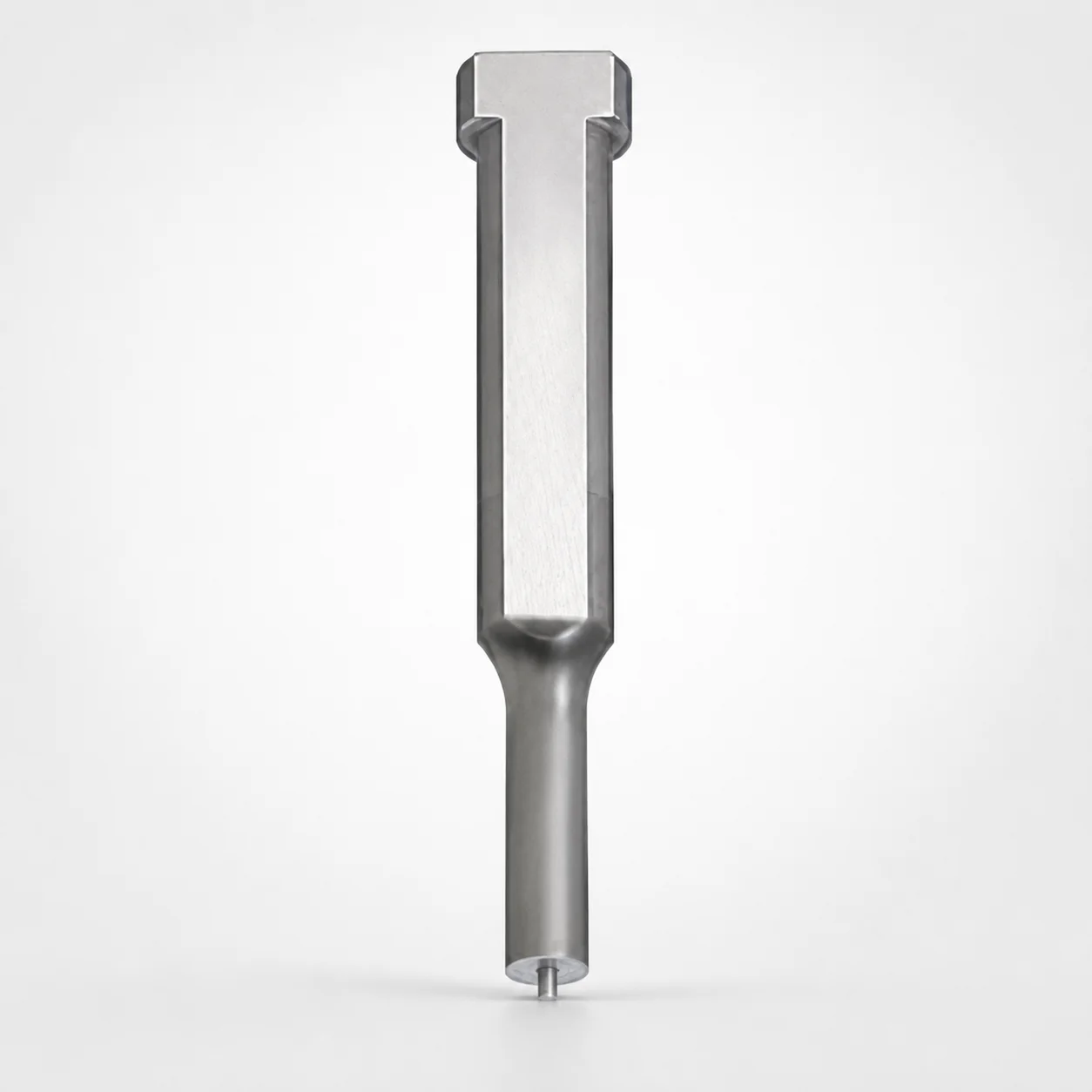
Key Flat Shank Ejector Punches - RW Coating
Key Flat Shank Ejector Punches (SKH40 equivalent powdered high-speed steel) with RW Coating are engineered for heavy-load mold applications where stable locating and reliable ejection are critical. The single-stepped shank design supports consistent punch behavior.
- Single-stepped shank geometry for stable guidance under load
- Spring-reinforced jector pin mechanism for dependable ejection
- Durable high-speed steel construction for wear-resistant service
- Optimized for keyed machining using common tip shapes
Specifications
6909 configurations available
| Jector | Tip shape | B (Tip length) | D (Shank diameter) (mm) | P (Tip dimension) (mm) | L (L dimension) (mm) | LC (Full length alteration) (mm) | LCT (Head thickness tolerance change + total length alteration) (mm) | LMT (Head thickness tolerance change + total length alteration) (mm) | PC (Tip dimension alteration) (mm) | R (Tip corner R) (mm) | W (Tip dimension) (mm) | WC (Tip dimension alteration) (mm) | type |
|---|---|---|---|---|---|---|---|---|---|---|---|---|---|
| Standard | Round | L | 4 | 1 ~ 2.8 | 50 ~ 80 | - | - | - | - | - | - | - | - |
| Standard | Round | L | 4 | 1 ~ 2.8 | - | 39 ~ 49.9 | - | - | - | - | - | - | - |
| Standard | Round | L | 4 | 1 ~ 2.8 | - | 50.1 ~ 59.9 | - | - | - | - | - | - | - |
| Standard | Round | L | 4 | 1 ~ 2.8 | - | 60.1 ~ 69.9 | - | - | - | - | - | - | - |
| Standard | Round | L | 4 | 1 ~ 2.8 | - | 70.1 ~ 79.9 | - | - | - | - | - | - | - |
| Standard | Round | L | 4 | 1 ~ 2.8 | - | - | 39 ~ 49.9 | - | - | - | - | - | - |
| Standard | Round | L | 4 | 1 ~ 2.8 | - | - | 50.1 ~ 59.9 | - | - | - | - | - | - |
| Standard | Round | L | 4 | 1 ~ 2.8 | - | - | 60.1 ~ 69.9 | - | - | - | - | - | - |
| Standard | Round | L | 4 | 1 ~ 2.8 | - | - | 70.1 ~ 79.9 | - | - | - | - | - | - |
| Standard | Round | L | 4 | 1 ~ 2.8 | - | - | - | 39 ~ 49.9 | - | - | - | - | - |
| Standard | Round | L | 4 | 1 ~ 2.8 | - | - | - | 50.1 ~ 59.9 | - | - | - | - | - |
| Standard | Round | L | 4 | 1 ~ 2.8 | - | - | - | 60.1 ~ 69.9 | - | - | - | - | - |
| Standard | Round | L | 4 | 1 ~ 2.8 | - | - | - | 70.1 ~ 79.9 | - | - | - | - | - |
| Standard | Round | L | 5 | 2 ~ 3.8 | 50 ~ 80 | - | - | - | - | - | - | - | - |
| Standard | Round | L | 5 | - | 50 ~ 80 | - | - | - | 1.8 ~ 1.99 | - | - | - | - |
| Standard | Round | L | 5 | 2 ~ 3.8 | - | 39 ~ 49.9 | - | - | - | - | - | - | - |
| Standard | Round | L | 5 | - | - | 39 ~ 49.9 | - | - | 1.8 ~ 1.99 | - | - | - | - |
| Standard | Round | L | 5 | 2 ~ 3.8 | - | 50.1 ~ 59.9 | - | - | - | - | - | - | - |
| Standard | Round | L | 5 | - | - | 50.1 ~ 59.9 | - | - | 1.8 ~ 1.99 | - | - | - | - |
| Standard | Round | L | 5 | 2 ~ 3.8 | - | 60.1 ~ 69.9 | - | - | - | - | - | - | - |
| Standard | Round | L | 5 | - | - | 60.1 ~ 69.9 | - | - | 1.8 ~ 1.99 | - | - | - | - |
| Standard | Round | L | 5 | 2 ~ 3.8 | - | 70.1 ~ 79.9 | - | - | - | - | - | - | - |
| Standard | Round | L | 5 | - | - | 70.1 ~ 79.9 | - | - | 1.8 ~ 1.99 | - | - | - | - |
| Standard | Round | L | 5 | 2 ~ 3.8 | - | - | 39 ~ 49.9 | - | - | - | - | - | - |
| Standard | Round | L | 5 | - | - | - | 39 ~ 49.9 | - | 1.8 ~ 1.99 | - | - | - | - |
| Standard | Round | L | 5 | 2 ~ 3.8 | - | - | 50.1 ~ 59.9 | - | - | - | - | - | - |
| Standard | Round | L | 5 | - | - | - | 50.1 ~ 59.9 | - | 1.8 ~ 1.99 | - | - | - | - |
| Standard | Round | L | 5 | 2 ~ 3.8 | - | - | 60.1 ~ 69.9 | - | - | - | - | - | - |
| Standard | Round | L | 5 | - | - | - | 60.1 ~ 69.9 | - | 1.8 ~ 1.99 | - | - | - | - |
| Standard | Round | L | 5 | 2 ~ 3.8 | - | - | 70.1 ~ 79.9 | - | - | - | - | - | - |
| Standard | Round | L | 5 | - | - | - | 70.1 ~ 79.9 | - | 1.8 ~ 1.99 | - | - | - | - |
| Standard | Round | L | 5 | 2 ~ 3.8 | - | - | - | 39 ~ 49.9 | - | - | - | - | - |
| Standard | Round | L | 5 | - | - | - | - | 39 ~ 49.9 | 1.8 ~ 1.99 | - | - | - | - |
| Standard | Round | L | 5 | 2 ~ 3.8 | - | - | - | 50.1 ~ 59.9 | - | - | - | - | - |
| Standard | Round | L | 5 | - | - | - | - | 50.1 ~ 59.9 | 1.8 ~ 1.99 | - | - | - | - |
| Standard | Round | L | 5 | 2 ~ 3.8 | - | - | - | 60.1 ~ 69.9 | - | - | - | - | - |
| Standard | Round | L | 5 | - | - | - | - | 60.1 ~ 69.9 | 1.8 ~ 1.99 | - | - | - | - |
| Standard | Round | L | 5 | 2 ~ 3.8 | - | - | - | 70.1 ~ 79.9 | - | - | - | - | - |
| Standard | Round | L | 5 | - | - | - | - | 70.1 ~ 79.9 | 1.8 ~ 1.99 | - | - | - | - |
| Standard | Round | L | 6 | 2 ~ 4.8 | 50 ~ 80 | - | - | - | - | - | - | - | - |
| Standard | Round | L | 6 | - | 50 ~ 80 | - | - | - | 1.8 ~ 1.99 | - | - | - | - |
| Standard | Round | L | 6 | 2 ~ 4.8 | - | 39 ~ 49.9 | - | - | - | - | - | - | - |
| Standard | Round | L | 6 | - | - | 39 ~ 49.9 | - | - | 1.8 ~ 1.99 | - | - | - | - |
| Standard | Round | L | 6 | 2 ~ 4.8 | - | 50.1 ~ 59.9 | - | - | - | - | - | - | - |
| Standard | Round | L | 6 | - | - | 50.1 ~ 59.9 | - | - | 1.8 ~ 1.99 | - | - | - | - |
| Standard | Round | L | 6 | 2 ~ 4.8 | - | 60.1 ~ 69.9 | - | - | - | - | - | - | - |
| Standard | Round | L | 6 | - | - | 60.1 ~ 69.9 | - | - | 1.8 ~ 1.99 | - | - | - | - |
| Standard | Round | L | 6 | 2 ~ 4.8 | - | 70.1 ~ 79.9 | - | - | - | - | - | - | - |
| Standard | Round | L | 6 | - | - | 70.1 ~ 79.9 | - | - | 1.8 ~ 1.99 | - | - | - | - |
| Standard | Round | L | 6 | 2 ~ 4.8 | - | - | 39 ~ 49.9 | - | - | - | - | - | - |
Product Guide
Application Scenarios+
These keyed flat shank ejector punches are used in injection mold tooling where the punch must stay aligned while transferring heavy ejection force. The single-stepped shank geometry helps maintain stable guidance under load, reducing misalignment-related wear.
- Automotive connector and sensor housing molds: Ideal for ejector systems that require repeatable stroke behavior and consistent tip engagement with keyed cavities.
- Appliance and industrial part molds: The spring-reinforced ejector pin option supports reliable ejection and helps recover after load cycling, improving robustness during high-run production.
- General heavy-load molding: RW-coated high-speed steel construction is suited for applications that demand improved wear resistance at the punch tip and shank guidance area.
Choose the spring-reinforced ejector mechanism variant when high ejection loads and frequent cycling can otherwise lead to inconsistent return or accelerated wear.
Material & Process Details+
This punch uses a SKH40-equivalent powdered high-speed steel base (as described for this series) combined with an RW coating. High-speed steels are selected for their combination of wear resistance and hot-strength behavior in sliding contact zones typical of ejector tools.
- Heat treatment state: The product description specifies SKH40-equivalent powdered HSS, consistent with tool-steel processing for wear service; the exact target hardness (HRC) and detailed heat-treatment parameters are not provided in the available data.
- Wear resistance vs. toughness: HSS offers strong wear resistance for punch tips and guidance faces, while requiring attention to impact loads where toughness could be lower than tougher tool steels.
- Coating role: RW coating is intended to further improve surface durability and reduce scuffing/abrasion during repeated ejection.
If you compare material options across suppliers, HSS + RW is typically chosen over lower-cost steels when service life at the tip and guidance surfaces is a priority.
Sizing & Selection Guide+
To select the correct keyed flat shank ejector punch, match the shank diameter D (4 ~ 25 mm) and the required tip geometry to your ejector hole and cavity contact profile. Confirm the tip dimension P (1 ~ 18 mm) and the configured tip length category (B: L or S).
- Tip shape selection: Choose from Round, Rectangle, Oblong, Double Flatted Round, Radius Rectangle to match your part ejection footprint.
- Length matching: Select the L (L dimension) range appropriate to your stack-up, with options including 50 ~ 80, 50 ~ 100, 60 ~ 100, 40 ~ 80, 40 ~ 100 mm.
- Total length adjustment: Use LC (27 ~ 90.1 mm) and associated head thickness tolerance change ranges LCT/LMT (27 ~ 90.1 mm) based on how your drawing accommodates tolerance compensation.
For fit, ensure D aligns with the ejector bore while accounting for your system’s machining allowances; exact tolerance values are not provided, so validate critical fits via your mold drawing standards.
Frequently Asked Questions
Which ejector mechanism should I choose for heavy-load molds: Standard or Spring Reinforced?+
For high-cycle, heavy-ejection applications, the Spring Reinforced ejector pin option is designed to support more dependable return behavior under load. The available parameter explicitly lists Jector: Standard and Spring Reinforced, so select the latter when you expect frequent cycling and higher ejection forces.
How do I select the correct shank diameter (D) and tip dimensions (P/W/WC) for my ejector bushing and contact area?+
Choose D (4 ~ 25 mm) to match the ejector bore size in your tooling. Then select the configured P (1 ~ 18 mm) along with the W (1 ~ 6 mm) and WC (1.8 ~ 9 mm) values to fit your required tip contact geometry.
What tip shapes and corner radius options are available for this ejector punch series?+
This series supports tip shapes including Round, Rectangle, Oblong, Double Flatted Round, and Radius Rectangle. The corner radius parameter is listed as R = 0.15 mm, which should be considered when matching sharpness/blend requirements for ejection clearance.
How should I choose L (overall L dimension) vs. LC/LCT/LMT when aligning the ejector stroke?+
Start by selecting L from the available ranges (50 ~ 80, 50 ~ 100, 60 ~ 100, 40 ~ 80, 40 ~ 100 mm) to reflect your baseline stack-up. Then use LC (27 ~ 90.1 mm) and the tolerance compensation ranges LCT or LMT (both 27 ~ 90.1 mm) to accommodate head thickness tolerance changes and total length alteration per your drawing.
What material and coating does this punch use, and what does RW coating imply for wear performance?+
The series is specified as SKH40 equivalent powdered high-speed steel with an RW coating. The coating is intended to improve surface durability in the ejector’s contact and sliding regions, supporting better wear resistance under repeated cycling compared with uncoated surfaces.
Related Products






Need Custom Specifications?
Our engineering team can help with custom configurations, material selection, and volume pricing.