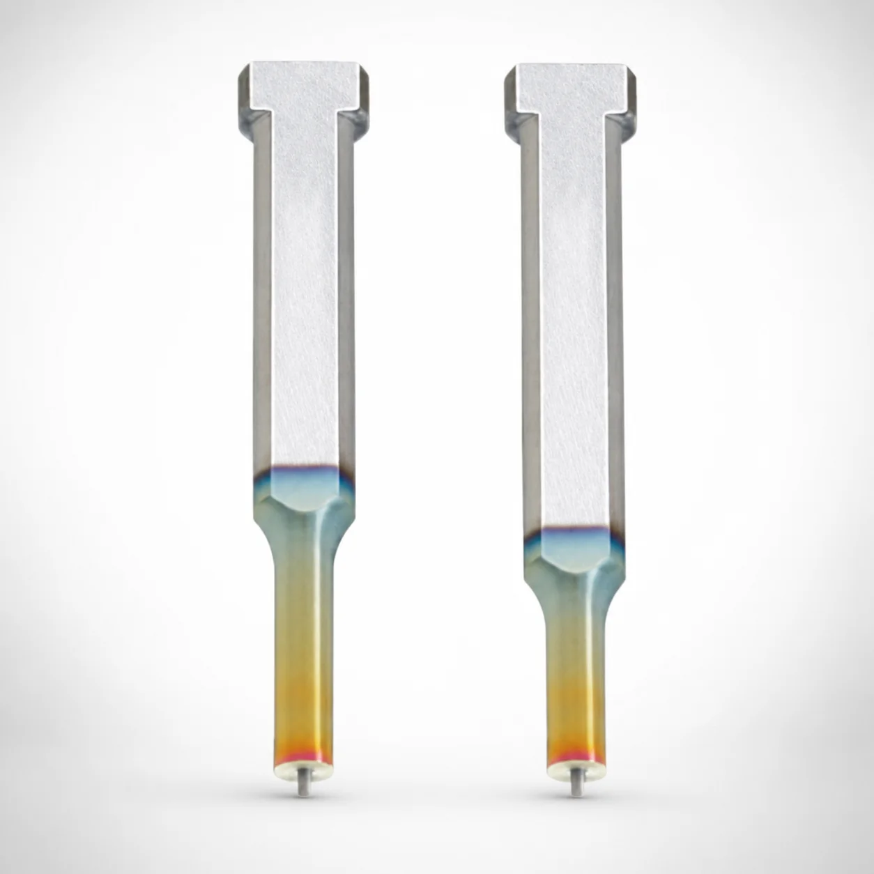
Key Flat Shank Ejector Punches DLC Coating
Key Flat Shank Ejector Punches (DLC coated) are designed for heavy loads, using a stable single-stepped shank and spring reinforced ejector pin to maintain consistent positioning. Powder high-speed steel construction supports reliable precision in production cycles.
- Stable single-stepped shank for controlled ejection under load
- DLC (XCD) coating improves wear resistance and surface durability
- Spring reinforced jector design supports repeatable punch guidance
- Common for die and press tooling where accuracy and fatigue resistance matter
Specifications
13818 configurations available
| Jector | Tip shape | Surface treatment | B (Tip length) | D (Shank diameter) (mm) | P (Tip dimension) (mm) | L (L dimension) (mm) | LC (Full length alteration) (mm) | LCT (Head thickness tolerance change + Total length alteration) (mm) | LMT (Head thickness tolerance change + Total length alteration) (mm) | PC (Tip dimension alteration) (mm) | R (Tip corner R) (mm) | W (Tip dimension) (mm) | WC (Tip dimension alteration) (mm) | type |
|---|---|---|---|---|---|---|---|---|---|---|---|---|---|---|
| Standard | Round | DLC (XCD) Coating | L | 4 | 1 ~ 2.8 | 50 ~ 80 | - | - | - | - | - | - | - | - |
| Standard | Round | DLC (XCD) Coating | L | 4 | 1 ~ 2.8 | - | 39 ~ 49.9 | - | - | - | - | - | - | - |
| Standard | Round | DLC (XCD) Coating | L | 4 | 1 ~ 2.8 | - | 50.1 ~ 59.9 | - | - | - | - | - | - | - |
| Standard | Round | DLC (XCD) Coating | L | 4 | 1 ~ 2.8 | - | 60.1 ~ 69.9 | - | - | - | - | - | - | - |
| Standard | Round | DLC (XCD) Coating | L | 4 | 1 ~ 2.8 | - | 70.1 ~ 79.9 | - | - | - | - | - | - | - |
| Standard | Round | DLC (XCD) Coating | L | 4 | 1 ~ 2.8 | - | - | 39 ~ 49.9 | - | - | - | - | - | - |
| Standard | Round | DLC (XCD) Coating | L | 4 | 1 ~ 2.8 | - | - | 50.1 ~ 59.9 | - | - | - | - | - | - |
| Standard | Round | DLC (XCD) Coating | L | 4 | 1 ~ 2.8 | - | - | 60.1 ~ 69.9 | - | - | - | - | - | - |
| Standard | Round | DLC (XCD) Coating | L | 4 | 1 ~ 2.8 | - | - | 70.1 ~ 79.9 | - | - | - | - | - | - |
| Standard | Round | DLC (XCD) Coating | L | 4 | 1 ~ 2.8 | - | - | - | 39 ~ 49.9 | - | - | - | - | - |
| Standard | Round | DLC (XCD) Coating | L | 4 | 1 ~ 2.8 | - | - | - | 50.1 ~ 59.9 | - | - | - | - | - |
| Standard | Round | DLC (XCD) Coating | L | 4 | 1 ~ 2.8 | - | - | - | 60.1 ~ 69.9 | - | - | - | - | - |
| Standard | Round | DLC (XCD) Coating | L | 4 | 1 ~ 2.8 | - | - | - | 70.1 ~ 79.9 | - | - | - | - | - |
| Standard | Round | DLC (XCD) Coating | L | 5 | 2 ~ 3.8 | 50 ~ 80 | - | - | - | - | - | - | - | - |
| Standard | Round | DLC (XCD) Coating | L | 5 | - | 50 ~ 80 | - | - | - | 1.8 ~ 1.99 | - | - | - | - |
| Standard | Round | DLC (XCD) Coating | L | 5 | 2 ~ 3.8 | - | 39 ~ 49.9 | - | - | - | - | - | - | - |
| Standard | Round | DLC (XCD) Coating | L | 5 | - | - | 39 ~ 49.9 | - | - | 1.8 ~ 1.99 | - | - | - | - |
| Standard | Round | DLC (XCD) Coating | L | 5 | 2 ~ 3.8 | - | 50.1 ~ 59.9 | - | - | - | - | - | - | - |
| Standard | Round | DLC (XCD) Coating | L | 5 | - | - | 50.1 ~ 59.9 | - | - | 1.8 ~ 1.99 | - | - | - | - |
| Standard | Round | DLC (XCD) Coating | L | 5 | 2 ~ 3.8 | - | 60.1 ~ 69.9 | - | - | - | - | - | - | - |
| Standard | Round | DLC (XCD) Coating | L | 5 | - | - | 60.1 ~ 69.9 | - | - | 1.8 ~ 1.99 | - | - | - | - |
| Standard | Round | DLC (XCD) Coating | L | 5 | 2 ~ 3.8 | - | 70.1 ~ 79.9 | - | - | - | - | - | - | - |
| Standard | Round | DLC (XCD) Coating | L | 5 | - | - | 70.1 ~ 79.9 | - | - | 1.8 ~ 1.99 | - | - | - | - |
| Standard | Round | DLC (XCD) Coating | L | 5 | 2 ~ 3.8 | - | - | 39 ~ 49.9 | - | - | - | - | - | - |
| Standard | Round | DLC (XCD) Coating | L | 5 | - | - | - | 39 ~ 49.9 | - | 1.8 ~ 1.99 | - | - | - | - |
| Standard | Round | DLC (XCD) Coating | L | 5 | 2 ~ 3.8 | - | - | 50.1 ~ 59.9 | - | - | - | - | - | - |
| Standard | Round | DLC (XCD) Coating | L | 5 | - | - | - | 50.1 ~ 59.9 | - | 1.8 ~ 1.99 | - | - | - | - |
| Standard | Round | DLC (XCD) Coating | L | 5 | 2 ~ 3.8 | - | - | 60.1 ~ 69.9 | - | - | - | - | - | - |
| Standard | Round | DLC (XCD) Coating | L | 5 | - | - | - | 60.1 ~ 69.9 | - | 1.8 ~ 1.99 | - | - | - | - |
| Standard | Round | DLC (XCD) Coating | L | 5 | 2 ~ 3.8 | - | - | 70.1 ~ 79.9 | - | - | - | - | - | - |
| Standard | Round | DLC (XCD) Coating | L | 5 | - | - | - | 70.1 ~ 79.9 | - | 1.8 ~ 1.99 | - | - | - | - |
| Standard | Round | DLC (XCD) Coating | L | 5 | 2 ~ 3.8 | - | - | - | 39 ~ 49.9 | - | - | - | - | - |
| Standard | Round | DLC (XCD) Coating | L | 5 | - | - | - | - | 39 ~ 49.9 | 1.8 ~ 1.99 | - | - | - | - |
| Standard | Round | DLC (XCD) Coating | L | 5 | 2 ~ 3.8 | - | - | - | 50.1 ~ 59.9 | - | - | - | - | - |
| Standard | Round | DLC (XCD) Coating | L | 5 | - | - | - | - | 50.1 ~ 59.9 | 1.8 ~ 1.99 | - | - | - | - |
| Standard | Round | DLC (XCD) Coating | L | 5 | 2 ~ 3.8 | - | - | - | 60.1 ~ 69.9 | - | - | - | - | - |
| Standard | Round | DLC (XCD) Coating | L | 5 | - | - | - | - | 60.1 ~ 69.9 | 1.8 ~ 1.99 | - | - | - | - |
| Standard | Round | DLC (XCD) Coating | L | 5 | 2 ~ 3.8 | - | - | - | 70.1 ~ 79.9 | - | - | - | - | - |
| Standard | Round | DLC (XCD) Coating | L | 5 | - | - | - | - | 70.1 ~ 79.9 | 1.8 ~ 1.99 | - | - | - | - |
| Standard | Round | DLC (XCD) Coating | L | 6 | 2 ~ 4.8 | 50 ~ 80 | - | - | - | - | - | - | - | - |
| Standard | Round | DLC (XCD) Coating | L | 6 | - | 50 ~ 80 | - | - | - | 1.8 ~ 1.99 | - | - | - | - |
| Standard | Round | DLC (XCD) Coating | L | 6 | 2 ~ 4.8 | - | 39 ~ 49.9 | - | - | - | - | - | - | - |
| Standard | Round | DLC (XCD) Coating | L | 6 | - | - | 39 ~ 49.9 | - | - | 1.8 ~ 1.99 | - | - | - | - |
| Standard | Round | DLC (XCD) Coating | L | 6 | 2 ~ 4.8 | - | 50.1 ~ 59.9 | - | - | - | - | - | - | - |
| Standard | Round | DLC (XCD) Coating | L | 6 | - | - | 50.1 ~ 59.9 | - | - | 1.8 ~ 1.99 | - | - | - | - |
| Standard | Round | DLC (XCD) Coating | L | 6 | 2 ~ 4.8 | - | 60.1 ~ 69.9 | - | - | - | - | - | - | - |
| Standard | Round | DLC (XCD) Coating | L | 6 | - | - | 60.1 ~ 69.9 | - | - | 1.8 ~ 1.99 | - | - | - | - |
| Standard | Round | DLC (XCD) Coating | L | 6 | 2 ~ 4.8 | - | 70.1 ~ 79.9 | - | - | - | - | - | - | - |
| Standard | Round | DLC (XCD) Coating | L | 6 | - | - | 70.1 ~ 79.9 | - | - | 1.8 ~ 1.99 | - | - | - | - |
| Standard | Round | DLC (XCD) Coating | L | 6 | 2 ~ 4.8 | - | - | 39 ~ 49.9 | - | - | - | - | - | - |
Product Guide
Application Scenarios+
Key flat shank ejector punches are used in injection and press tooling where an ejector system must deliver consistent stroke positioning under repeated high-load cycles. The spring reinforced variant supports stable stepped guidance, helping reduce deflection and maintaining alignment between the ejector face and the molded part.
- Automotive connector and small housing molds: DLC (XCD) surface treatment improves wear resistance on the punch tip during frequent ejection cycles, supporting long-term dimensional stability around the ejector area.
- Appliance and electronics part molds: The round/rectangle/oblong and double-flatted tip shapes allow designers to match part geometry while the single-stepped shank helps control ejector movement in the guide.
- General die/press applications with heavy loads: Choose the spring reinforced jector to enhance repeatability, especially where load variations can otherwise disturb punch guidance.
This combination—spring reinforced guidance plus DLC wear protection—makes the product well-suited for tooling that requires fatigue resistance and controlled ejector behavior.
Material & Process Details+
The base material is described as powder high-speed steel (HSS), selected for reliable precision across production cycles. HSS tooling generally offers a favorable balance of wear resistance and toughness, though higher hardness often reduces impact toughness—so the coating and reinforcement design are important for heavy-duty ejection.
- DLC (XCD) coating: provides a hard, low-friction wear surface to protect the punch tip and shank contact areas during repeated ejection.
- DLC + WPC (optional): adds an additional protection layer, typically chosen when surface durability requirements are higher than DLC alone.
- Heat treatment state: not explicitly specified in the provided data; verify coating compatibility and substrate hardness at the time of ordering.
For abrasion-dominant cycles, DLC (XCD) is the first selection. For harsher environments where additional surface protection is desired, the DLC + WPC variant can be considered.
Sizing & Selection Guide+
Select the punch size by matching the ejector tip geometry and shank diameter to your die insert design and the ejector guide system. Start with the D (shank diameter) in the range 4–25 mm; this must fit the corresponding guide/bushing ID and maintain stable stepped guidance.
- Tip shape: choose from round, rectangle, oblong, double-flatted round, or radius rectangle to match the part ejection contact area.
- Tip dimensions: use P = 1–18 mm, with additional dimensional parameters PC = 1.8–9 mm and W = 1–6 mm, WC = 1.8–5 mm depending on the selected tip form.
- Overall length & head fit: available L ranges include 50–80, 50–100, 60–100, 40–80, and 40–100 mm. Confirm LC = 27–90.1 mm (full length alteration) and LCT/LMT = 27–90.1 mm (tolerance/alteration references) against your press/die stack-up.
- Tolerances/fit: head thickness tolerance change parameters (LCT and LMT) indicate how total length may be altered to achieve the required fit; select the variant that preserves your critical clearances.
If your design requires a specific contact width or corner radius, use the provided R = 0.15 mm and the tip alteration values to ensure controlled engagement.
Frequently Asked Questions
Which ejector variant should I choose: standard or spring reinforced, for heavy-load injection molding cycles?+
How does the DLC coating (XCD) compare with DLC + WPC for wear resistance on ejector punches?+
What shank diameter range (D) is available, and how do I ensure it matches my guide/bushing?+
How do I select the correct punch length (L, LC, LCT/LMT) for my die stack-up?+
Which tip shapes and dimensions (P, PC, W/WC, R) are appropriate for part ejector contact features?+
Related Products






Need Custom Specifications?
Our engineering team can help with custom configurations, material selection, and volume pricing.