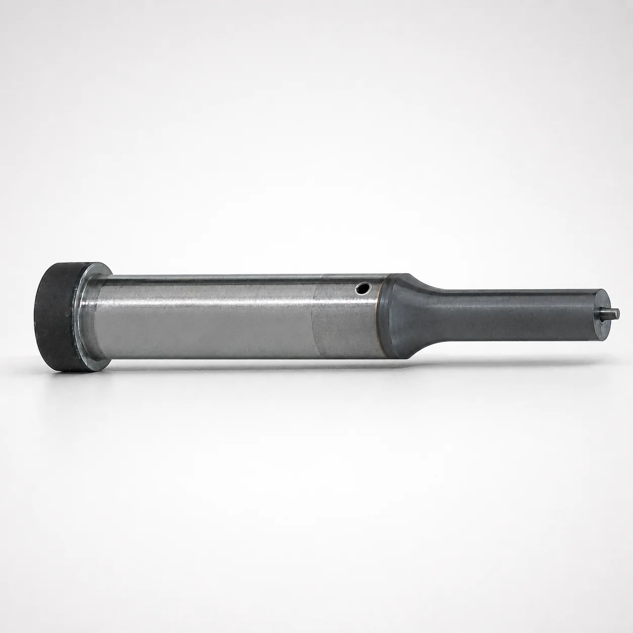
JIS Standard Steel Jector Punches Single-Stepped HW Coating
Jector Punches Single-stepped (powdered high-speed steel) with HW coating are designed for reliable punch performance in precision mold and stamping tooling. The single-step shank supports consistent alignment under load.
- Single-stepped shank for stable mounting in standard jector punch blocks
- HW coating with high-wear performance from hardfacing-style surface protection
- Precision-fit tolerances support consistent assembly and accurate punching
- Suitable for standard or spring reinforced jector tooling configurations
Specifications
4936 configurations available
| Jector | Tip shape | Shank diameter D tolerance | B (Tip length) | D (Shank diameter) (mm) | P (Tip dimension) (mm) | L (L dimension) (mm) | LC (Full length alteration) (mm) | LCT (Head thickness tolerance change + total length alteration) (mm) | LMT(Head thickness tolerance change+Full length change) (mm) | PC (Tip dimension alteration) (mm) | R (Tip corner R) (mm) | W (Tip dimension) (mm) | WC (Tip dimension alteration) (mm) | type |
|---|---|---|---|---|---|---|---|---|---|---|---|---|---|---|
| Standard | Round | +0.005/0 | L | 4 | 1 ~ 3.99 | 50 ~ 80 | - | - | - | - | - | - | - | - |
| Standard | Round | +0.005/0 | L | 4 | - | 50 ~ 80 | - | - | - | 0.9 ~ 0.99 | - | - | - | - |
| Standard | Round | +0.005/0 | L | 4 | 1 ~ 3.99 | - | 39 ~ 79.9 | - | - | - | - | - | - | - |
| Standard | Round | +0.005/0 | L | 4 | - | - | 39 ~ 79.9 | - | - | 0.9 ~ 0.99 | - | - | - | - |
| Standard | Round | +0.005/0 | L | 4 | 1 ~ 3.99 | - | - | 39 ~ 79.9 | - | - | - | - | - | - |
| Standard | Round | +0.005/0 | L | 4 | - | - | - | 39 ~ 79.9 | - | 0.9 ~ 0.99 | - | - | - | - |
| Standard | Round | +0.005/0 | L | 4 | 1 ~ 3.99 | - | - | - | 39 ~ 79.9 | - | - | - | - | - |
| Standard | Round | +0.005/0 | L | 4 | - | - | - | - | 39 ~ 79.9 | 0.9 ~ 0.99 | - | - | - | - |
| Standard | Round | +0.005/0 | L | 5 | 2 ~ 4.99 | 50 ~ 80 | - | - | - | - | - | - | - | - |
| Standard | Round | +0.005/0 | L | 5 | - | 50 ~ 80 | - | - | - | 1.8 ~ 1.99 | - | - | - | - |
| Standard | Round | +0.005/0 | L | 5 | 2 ~ 4.99 | - | 39 ~ 79.9 | - | - | - | - | - | - | - |
| Standard | Round | +0.005/0 | L | 5 | - | - | 39 ~ 79.9 | - | - | 1.8 ~ 1.99 | - | - | - | - |
| Standard | Round | +0.005/0 | L | 5 | 2 ~ 4.99 | - | - | 39 ~ 79.9 | - | - | - | - | - | - |
| Standard | Round | +0.005/0 | L | 5 | - | - | - | 39 ~ 79.9 | - | 1.8 ~ 1.99 | - | - | - | - |
| Standard | Round | +0.005/0 | L | 5 | 2 ~ 4.99 | - | - | - | 39 ~ 79.9 | - | - | - | - | - |
| Standard | Round | +0.005/0 | L | 5 | - | - | - | - | 39 ~ 79.9 | 1.8 ~ 1.99 | - | - | - | - |
| Standard | Round | +0.005/0 | L | 6 | 2 ~ 5.99 | 50 ~ 80 | - | - | - | - | - | - | - | - |
| Standard | Round | +0.005/0 | L | 6 | - | 50 ~ 80 | - | - | - | 1.8 ~ 1.99 | - | - | - | - |
| Standard | Round | +0.005/0 | L | 6 | 2 ~ 5.99 | - | 39 ~ 79.9 | - | - | - | - | - | - | - |
| Standard | Round | +0.005/0 | L | 6 | - | - | 39 ~ 79.9 | - | - | 1.8 ~ 1.99 | - | - | - | - |
| Standard | Round | +0.005/0 | L | 6 | 2 ~ 5.99 | - | - | 39 ~ 79.9 | - | - | - | - | - | - |
| Standard | Round | +0.005/0 | L | 6 | - | - | - | 39 ~ 79.9 | - | 1.8 ~ 1.99 | - | - | - | - |
| Standard | Round | +0.005/0 | L | 6 | 2 ~ 5.99 | - | - | - | 39 ~ 79.9 | - | - | - | - | - |
| Standard | Round | +0.005/0 | L | 6 | - | - | - | - | 39 ~ 79.9 | 1.8 ~ 1.99 | - | - | - | - |
| Standard | Round | +0.005/0 | L | 8 | 3 ~ 7.99 | 50 ~ 100 | - | - | - | - | - | - | - | - |
| Standard | Round | +0.005/0 | L | 8 | - | 50 ~ 100 | - | - | - | 2.5 ~ 2.99 | - | - | - | - |
| Standard | Round | +0.005/0 | L | 8 | 3 ~ 7.99 | - | 33 ~ 99.9 | - | - | - | - | - | - | - |
| Standard | Round | +0.005/0 | L | 8 | - | - | 33 ~ 99.9 | - | - | 2.5 ~ 2.99 | - | - | - | - |
| Standard | Round | +0.005/0 | L | 8 | 3 ~ 7.99 | - | - | 33 ~ 99.9 | - | - | - | - | - | - |
| Standard | Round | +0.005/0 | L | 8 | - | - | - | 33 ~ 99.9 | - | 2.5 ~ 2.99 | - | - | - | - |
| Standard | Round | +0.005/0 | L | 8 | 3 ~ 7.99 | - | - | - | 33 ~ 99.9 | - | - | - | - | - |
| Standard | Round | +0.005/0 | L | 8 | - | - | - | - | 33 ~ 99.9 | 2.5 ~ 2.99 | - | - | - | - |
| Standard | Round | +0.005/0 | L | 10 | 3 ~ 9.99 | 50 ~ 100 | - | - | - | - | - | - | - | - |
| Standard | Round | +0.005/0 | L | 10 | - | 50 ~ 100 | - | - | - | 2.8 ~ 2.99 | - | - | - | - |
| Standard | Round | +0.005/0 | L | 10 | 3 ~ 9.99 | - | 33 ~ 99.9 | - | - | - | - | - | - | - |
| Standard | Round | +0.005/0 | L | 10 | - | - | 33 ~ 99.9 | - | - | 2.8 ~ 2.99 | - | - | - | - |
| Standard | Round | +0.005/0 | L | 10 | 3 ~ 9.99 | - | - | 33 ~ 99.9 | - | - | - | - | - | - |
| Standard | Round | +0.005/0 | L | 10 | - | - | - | 33 ~ 99.9 | - | 2.8 ~ 2.99 | - | - | - | - |
| Standard | Round | +0.005/0 | L | 10 | 3 ~ 9.99 | - | - | - | 33 ~ 99.9 | - | - | - | - | - |
| Standard | Round | +0.005/0 | L | 10 | - | - | - | - | 33 ~ 99.9 | 2.8 ~ 2.99 | - | - | - | - |
| Standard | Round | +0.005/0 | L | 13 | 6 ~ 12.99 | 50 ~ 100 | - | - | - | - | - | - | - | - |
| Standard | Round | +0.005/0 | L | 13 | - | 50 ~ 100 | - | - | - | 5 ~ 5.99 | - | - | - | - |
| Standard | Round | +0.005/0 | L | 13 | 6 ~ 12.99 | - | 33 ~ 99.9 | - | - | - | - | - | - | - |
| Standard | Round | +0.005/0 | L | 13 | - | - | 33 ~ 99.9 | - | - | 5 ~ 5.99 | - | - | - | - |
| Standard | Round | +0.005/0 | L | 13 | 6 ~ 12.99 | - | - | 33 ~ 99.9 | - | - | - | - | - | - |
| Standard | Round | +0.005/0 | L | 13 | - | - | - | 33 ~ 99.9 | - | 5 ~ 5.99 | - | - | - | - |
| Standard | Round | +0.005/0 | L | 13 | 6 ~ 12.99 | - | - | - | 33 ~ 99.9 | - | - | - | - | - |
| Standard | Round | +0.005/0 | L | 13 | - | - | - | - | 33 ~ 99.9 | 5 ~ 5.99 | - | - | - | - |
| Standard | Round | +0.005/0 | L | 16 | 10 ~ 15.99 | 60 ~ 100 | - | - | - | - | - | - | - | - |
| Standard | Round | +0.005/0 | L | 16 | - | 60 ~ 100 | - | - | - | 8 ~ 9.99 | - | - | - | - |
Product Guide
Application Scenarios+
These JIS standard jector punches are used in injection mold tooling and precision stamping systems where a controlled ejection force and repeatable alignment are required. The single-stepped shank is intended to seat consistently in standard jector punch blocks, helping maintain punch-to-block positioning during cycling.
- Automotive and consumer electronics tooling: In multi-cavity molds or fine-pitch progressive stamping dies, the HW-coated surface supports stable insertion and improved wear where punches experience frequent contact against guide bushings and ejector passages.
- Medical device housings & precision molded parts: The stable mounting geometry helps reduce dimensional drift over time, supporting consistent punching of small features with defined tip profiles (round, rectangle, oblong, double-flatted round, and radius rectangle).
- Spring-reinforced jector configurations: When used in spring reinforced jector tool setups, the shank design supports accurate engagement while the HW coating improves resistance to abrasive wear.
Material & Process Details+
This product is described as a JIS Standard Steel jector punch made from powdered high-speed steel with a HW coating for punch tooling applications. Powdered HSS manufacturing provides a refined microstructure, supporting high hardness and improved wear resistance compared with conventional steels.
- Coating function (HW): The HW surface protection is intended to reduce wear during insertion and repeated contact, improving service life in guided punch environments.
- Hardness & wear/toughness balance: While specific HRC values are not provided in the input data, the typical HSS + wear-coating approach prioritizes wear resistance. That can trade off against impact toughness if used in highly shock-loaded or misaligned setups—proper guidance and fit are important.
- Heat treatment state: The input specifies powdered HSS but does not list an exact heat-treatment condition (e.g., quench & temper, nitriding). When specifying, confirm the supplier’s standard hardening process for the JIS grade.
Sizing & Selection Guide+
Select the jector punch size by matching the shank diameter, tip geometry, and overall lengths to the jector punch block and cavity/core requirement. The shank diameter D is available from 4–25 mm with tolerance +0.005/0 and m5, so choose D to fit the block bore/guide with the intended clearance.
- Choose shank diameter (D): Pick the D that corresponds to your jector punch block seating and guide alignment needs, accounting for the given tolerance (m5 / +0.005/0).
- Select tip profile and tip dimensions: Tip shape can be Round, Rectangle, Oblong, Double Flatted Round, or Radius Rectangle. Tip-related dimensions include P = 1–18 mm and W = 1–6 mm, with tip corner radius R = 0.15 mm.
- Match lengths: Head/tip length options include B (Tip length) = L or S, and overall L offers ranges such as 50–80, 50–100, 60–100, 40–80, 40–100 and 50–80 (as listed). Use LC (33–74 mm) and LCT/LMT alteration ranges (33–74 mm) to confirm the intended total length adjustment and assembly stack-up.
Frequently Asked Questions
How do I choose the correct shank diameter D and tolerance (+0.005/0, m5) for my jector punch block?+
Which tip shapes and dimensions are available, and what should I check for small feature punching?+
For stable ejection, what is the advantage of the single-stepped shank in standard vs spring reinforced setups?+
How do I select overall length L (and LC/LCT/LMT alteration) to match my mold stack-up?+
What does the HW coating change for wear life, and where is it most beneficial?+
Related Products






Need Custom Specifications?
Our engineering team can help with custom configurations, material selection, and volume pricing.