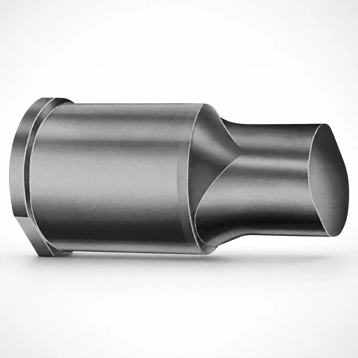
Extended Range Punches - Metric XNA Coating
Extended Range Punches - Metric (XNA coating) are precision punch tools designed for consistent performance in forming and punching operations. The extended geometry supports stable guidance across longer stroke ranges while maintaining dependable cutting edge protection.
- Extended range punch design supports stable alignment during punching cycles
- XNA coating helps improve abrasion resistance and surface protection
- Manufactured for consistent fit in standard tool setups and die assemblies
- Metric punch style for typical industrial punching and forming applications
Specifications
50 configurations available
| Tip shape | D (Shank dia.) (mm) | L1 (Point Length) (mm) | L (Length) (mm) | P Dimension (mm) | W Dimension (mm) | R Dimension (mm) |
|---|---|---|---|---|---|---|
| H | 40 | 25 ~ 30 | 63 ~ 100 | 20 ~ 39.95 | 8 ~ 39.95 | - |
| H | 45 | 25 ~ 30 | 63 ~ 100 | 25 ~ 44.95 | 9 ~ 44.95 | - |
| H | 50 | 25 ~ 30 | 63 ~ 100 | 30 ~ 49.95 | 10 ~ 49.95 | - |
| H | 56 | 25 ~ 30 | 63 ~ 100 | 35 ~ 55.95 | 11 ~ 55.95 | - |
| H | 63 | 25 ~ 30 | 63 ~ 100 | 40 ~ 62.95 | 12 ~ 62.95 | - |
| J | 40 | 25 ~ 30 | 63 ~ 100 | 20 ~ 39.95 | 8 ~ 39.95 | - |
| J | 45 | 25 ~ 30 | 63 ~ 100 | 25 ~ 44.95 | 9 ~ 44.95 | - |
| J | 50 | 25 ~ 30 | 63 ~ 100 | 30 ~ 49.95 | 10 ~ 49.95 | - |
| J | 56 | 25 ~ 30 | 63 ~ 100 | 35 ~ 55.95 | 11 ~ 55.95 | - |
| J | 63 | 25 ~ 30 | 63 ~ 100 | 40 ~ 62.95 | 12 ~ 62.95 | - |
| K | 40 | 25 ~ 30 | 63 ~ 100 | 20 ~ 39.95 | 8 ~ 39.95 | 0.2 ~ 19.975 |
| K | 45 | 25 ~ 30 | 63 ~ 100 | 25 ~ 44.95 | 9 ~ 44.95 | 0.2 ~ 22.475 |
| K | 50 | 25 ~ 30 | 63 ~ 100 | 30 ~ 49.95 | 10 ~ 49.95 | 0.2 ~ 24.975 |
| K | 56 | 25 ~ 30 | 63 ~ 100 | 35 ~ 55.95 | 11 ~ 55.95 | 0.2 ~ 27.975 |
| K | 63 | 25 ~ 30 | 63 ~ 100 | 40 ~ 62.95 | 12 ~ 62.95 | 0.2 ~ 31.475 |
| N | 40 | 25 ~ 30 | 63 ~ 100 | - | 8 ~ 39.95 | - |
| N | 45 | 25 ~ 30 | 63 ~ 100 | - | 9 ~ 44.95 | - |
| N | 50 | 25 ~ 30 | 63 ~ 100 | - | 10 ~ 49.95 | - |
| N | 56 | 25 ~ 30 | 63 ~ 100 | - | 11 ~ 55.95 | - |
| N | 63 | 25 ~ 30 | 63 ~ 100 | - | 12 ~ 62.95 | - |
| O | 40 | 25 ~ 30 | 63 ~ 100 | 20 ~ 39.95 | 8 ~ 39.95 | - |
| O | 45 | 25 ~ 30 | 63 ~ 100 | 25 ~ 44.95 | 9 ~ 44.95 | - |
| O | 50 | 25 ~ 30 | 63 ~ 100 | 30 ~ 49.95 | 10 ~ 49.95 | - |
| O | 56 | 25 ~ 30 | 63 ~ 100 | 35 ~ 55.95 | 11 ~ 55.95 | - |
| O | 63 | 25 ~ 30 | 63 ~ 100 | 40 ~ 62.95 | 12 ~ 62.95 | - |
| R | 40 | 25 ~ 30 | 63 ~ 100 | 20 ~ 39.95 | 8 ~ 39.95 | - |
| R | 45 | 25 ~ 30 | 63 ~ 100 | 25 ~ 44.95 | 9 ~ 44.95 | - |
| R | 50 | 25 ~ 30 | 63 ~ 100 | 30 ~ 49.95 | 10 ~ 49.95 | - |
| R | 56 | 25 ~ 30 | 63 ~ 100 | 35 ~ 55.95 | 11 ~ 55.95 | - |
| R | 63 | 25 ~ 30 | 63 ~ 100 | 40 ~ 62.95 | 12 ~ 62.95 | - |
| V | 40 | 25 ~ 30 | 63 ~ 100 | 20 ~ 39.95 | 8 ~ 39.95 | - |
| V | 45 | 25 ~ 30 | 63 ~ 100 | 25 ~ 44.95 | 9 ~ 44.95 | - |
| V | 50 | 25 ~ 30 | 63 ~ 100 | 30 ~ 49.95 | 10 ~ 49.95 | - |
| V | 56 | 25 ~ 30 | 63 ~ 100 | 35 ~ 55.95 | 11 ~ 55.95 | - |
| V | 63 | 25 ~ 30 | 63 ~ 100 | 40 ~ 62.95 | 12 ~ 62.95 | - |
| X | 40 | 25 ~ 30 | 63 ~ 100 | 20 ~ 39.95 | - | - |
| X | 45 | 25 ~ 30 | 63 ~ 100 | 25 ~ 44.95 | - | - |
| X | 50 | 25 ~ 30 | 63 ~ 100 | 30 ~ 49.95 | - | - |
| X | 56 | 25 ~ 30 | 63 ~ 100 | 35 ~ 55.95 | - | - |
| X | 63 | 25 ~ 30 | 63 ~ 100 | 40 ~ 62.95 | - | - |
| Y | 40 | 25 ~ 30 | 63 ~ 100 | 20 ~ 39.95 | 8 ~ 39.95 | 0.2 ~ 19.975 |
| Y | 45 | 25 ~ 30 | 63 ~ 100 | 25 ~ 44.95 | 9 ~ 44.95 | 0.2 ~ 22.475 |
| Y | 50 | 25 ~ 30 | 63 ~ 100 | 30 ~ 49.95 | 10 ~ 49.95 | 0.2 ~ 24.975 |
| Y | 56 | 25 ~ 30 | 63 ~ 100 | 35 ~ 55.95 | 11 ~ 55.95 | 0.2 ~ 27.975 |
| Y | 63 | 25 ~ 30 | 63 ~ 100 | 40 ~ 62.95 | 12 ~ 62.95 | 0.2 ~ 31.475 |
| Z | 40 | 25 ~ 30 | 63 ~ 100 | - | 8 ~ 39.95 | 0.2 ~ 19.975 |
| Z | 45 | 25 ~ 30 | 63 ~ 100 | - | 9 ~ 44.95 | 0.2 ~ 22.475 |
| Z | 50 | 25 ~ 30 | 63 ~ 100 | - | 10 ~ 49.95 | 0.2 ~ 24.975 |
| Z | 56 | 25 ~ 30 | 63 ~ 100 | - | 11 ~ 55.95 | 0.2 ~ 27.975 |
| Z | 63 | 25 ~ 30 | 63 ~ 100 | - | 12 ~ 62.95 | 0.2 ~ 31.475 |
Product Guide
Application Scenarios+
These metric extended-range punches are used in progressive and single-station forming and punching tooling where stable guidance over a longer stroke is critical. The extended length (L ranges from 63 to 100 mm) helps maintain alignment during repeated cutting cycles, reducing risk of edge wandering and uneven wear.
Common application scenarios include:
- Automotive bracket and connector forming: XNA-coated surfaces provide abrasion protection for high-cycle stamping where punch-to-die friction is significant.
- Sheet metal punching in appliance and HVAC fabrication: The extended geometry supports dependable edge conditioning across longer stroke ranges while keeping standard die-set compatibility.
- General industrial part blanking: Metric shank diameters (D = 40, 45, 50, 56, 63 mm) support robust tool guidance in heavier duty tool blocks.
The XNA coating variant is particularly suited when wear resistance and surface protection matter for stable punch performance in extended forming/punching cycles.
Material & Process Details+
Material and heat-treatment specifics are not provided in the supplied data, so selection should be confirmed against the manufacturer’s technical drawing for this series. In general, XNA-type coatings are applied to enhance surface wear resistance and protect the punch body from abrasion during punching and forming.
When engineering these punches, the key trade-off to validate is that higher wear resistance coatings can slightly alter surface friction characteristics, affecting lubrication behavior and die wear patterns. Ensure the coating system is compatible with your press speed, material grade, and lubrication strategy to maintain cutting-edge stability.
- Coating state: XNA coating (as specified) for abrasion resistance and surface protection.
- Hardness (HRC): Not specified in the provided parameters—confirm on the datasheet for expected wear/toughness balance.
- Toughness vs. wear: typically optimized via base steel heat treatment (quench & temper) and finish grinding; verify for your load and shock conditions.
If you’re comparing variants within the same series, select the coating hardness and base hardness that best match your material to be punched and your allowable wear rate.
Sizing & Selection Guide+
Correct sizing for extended-range punches starts with matching the punch shank diameter D and overall length to the die setup and guidance requirements. For this series, choose D from 40, 45, 50, 56, or 63 mm.
- Overall length (L): select within 63 to 100 mm to achieve the intended guidance/support length in your upper tool holder and stripper plate system.
- Point length (L1): fixed at 25 to 30 mm, used to set effective penetration/working geometry relative to the die opening.
- Tip shape: choose H, J, K, N, O, R, V, X, or Z based on clearance, part geometry, and chip control needs.
To align with cavity/core requirements, verify the P and W dimensions fall within the available ranges for your chosen configuration (P and W vary by variant), and ensure the R value matches your required corner radius (R ranges from 0.2 up to 31.475 mm depending on the variant).
Where multiple dimensions are adjustable by variant, confirm dimensional fit against your tool drawing (especially around clearance-sensitive interfaces) to avoid interference or excessive side loading; tolerances are not specified in the provided data and must be confirmed from the series documentation.
Frequently Asked Questions
Which shank diameter (D) options are available for these metric extended-range punches, and how do I choose between them?+
The available shank diameter options are D = 40, 45, 50, 56, or 63 mm. Select the diameter that matches your tool holder/bushing guidance requirements for the die set and provides the stiffness needed for the expected punching load. Using an undersized D can increase deflection and accelerate wear at the cutting edge.
How should I select the overall punch length (L) for extended stroke guidance in a progressive die?+
This series provides L = 63 to 100 mm. Choose L based on the available guidance length within your upper housing/stripper tooling while keeping the working point (L1) correct for die clearance and penetration. The extended length is intended to stabilize alignment across longer stroke ranges.
What is the fixed point length (L1) range and how does it affect die clearance and penetration?+
The point length is specified as L1 = 25 to 30 mm (fixed range for this product line). L1 largely determines the effective punch working reach relative to the die opening and stripper engagement. Use it together with your die clearance targets to avoid insufficient piercing or excessive bottoming.
What does the XNA coating contribute for punching and forming, and where is it most beneficial?+
The XNA coating is specified to improve abrasion resistance and surface protection. It is most beneficial in high-cycle punching and forming where friction and sliding at the punch/die interfaces cause rapid surface wear. Confirm coating compatibility with your lubrication regime and sheet material grade to maintain stable cutting performance.
How do I match P, W, and R dimensions when selecting a specific variant of this extended-range punch?+
This series lists variant-specific ranges for P, W, and R. Choose the configuration where your required P and W values fall within the provided ranges (P and W vary by variant), and verify the corner radius R matches your part edge/chip-control requirements (R ranges up to 31.475 mm depending on the variant). Because tolerances are not included in the provided data, confirm final dimensional limits against the official series drawing before building the tool.
Related Products






Need Custom Specifications?
Our engineering team can help with custom configurations, material selection, and volume pricing.