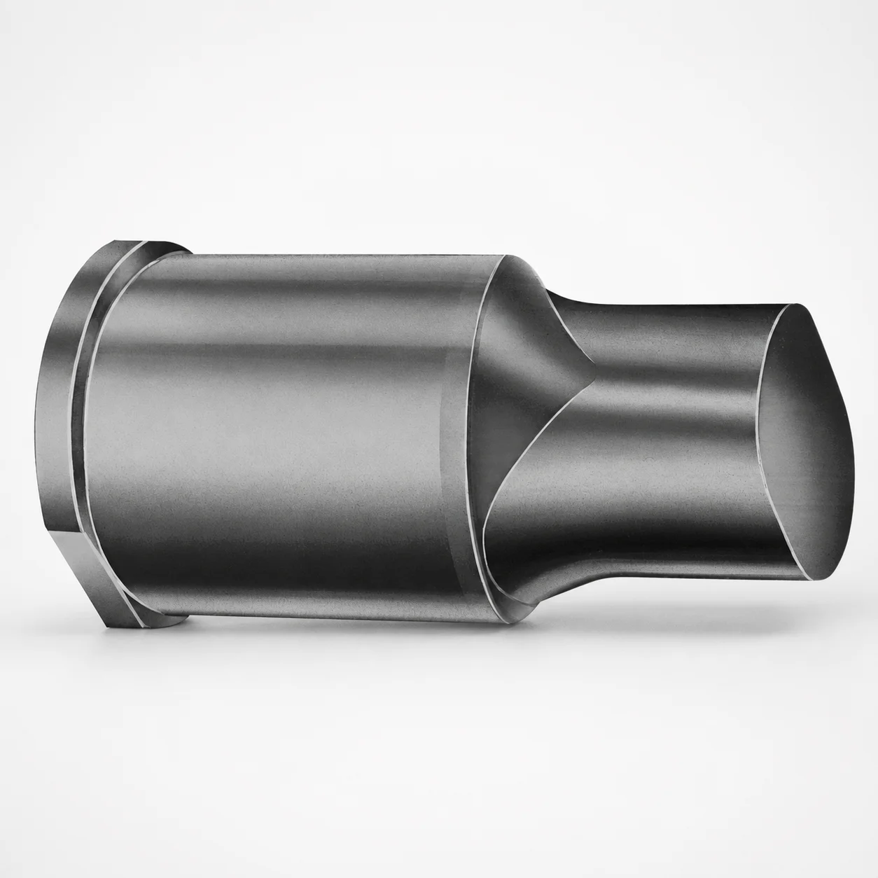
JIS Standard Steel Extended Range Punches X-Tip
Extended range punches X-tip (steel) are designed for die makers who need reliable punch action over a longer reach. The X-shaped tip option helps maintain consistent material shearing at production conditions.
- Extended reach punch geometry supports stable punching in deeper layouts
- Steel body with robust wear behavior for long service intervals
- Designed for tight die assembly compatibility with standard tool setups
- Used for metric progressive dies and press tooling requiring repeatable punch edges
Specifications
50 configurations available
| Tip shape | D (Shank dia.) (mm) | L1 (Point Length) (mm) | L (Length) (mm) | P Dimension (mm) | W Dimension (mm) | R Dimension (mm) |
|---|---|---|---|---|---|---|
| H | 40 | 25 ~ 30 | 63 ~ 100 | 20 ~ 39.95 | 8 ~ 39.95 | - |
| H | 45 | 25 ~ 30 | 63 ~ 100 | 25 ~ 44.95 | 9 ~ 44.95 | - |
| H | 50 | 25 ~ 30 | 63 ~ 100 | 30 ~ 49.95 | 10 ~ 49.95 | - |
| H | 56 | 25 ~ 30 | 63 ~ 100 | 35 ~ 55.95 | 11 ~ 55.95 | - |
| H | 63 | 25 ~ 30 | 63 ~ 100 | 40 ~ 62.95 | 12 ~ 62.95 | - |
| J | 40 | 25 ~ 30 | 63 ~ 100 | 20 ~ 39.95 | 8 ~ 39.95 | - |
| J | 45 | 25 ~ 30 | 63 ~ 100 | 25 ~ 44.95 | 9 ~ 44.95 | - |
| J | 50 | 25 ~ 30 | 63 ~ 100 | 30 ~ 49.95 | 10 ~ 49.95 | - |
| J | 56 | 25 ~ 30 | 63 ~ 100 | 35 ~ 55.95 | 11 ~ 55.95 | - |
| J | 63 | 25 ~ 30 | 63 ~ 100 | 40 ~ 62.95 | 12 ~ 62.95 | - |
| K | 40 | 25 ~ 30 | 63 ~ 100 | 20 ~ 39.95 | 8 ~ 39.95 | 0.2 ~ 19.975 |
| K | 45 | 25 ~ 30 | 63 ~ 100 | 25 ~ 44.95 | 9 ~ 44.95 | 0.2 ~ 22.475 |
| K | 50 | 25 ~ 30 | 63 ~ 100 | 30 ~ 49.95 | 10 ~ 49.95 | 0.2 ~ 24.975 |
| K | 56 | 25 ~ 30 | 63 ~ 100 | 35 ~ 55.95 | 11 ~ 55.95 | 0.2 ~ 27.975 |
| K | 63 | 25 ~ 30 | 63 ~ 100 | 40 ~ 62.95 | 12 ~ 62.95 | 0.2 ~ 31.475 |
| N | 40 | 25 ~ 30 | 63 ~ 100 | - | 8 ~ 39.95 | - |
| N | 45 | 25 ~ 30 | 63 ~ 100 | - | 9 ~ 44.95 | - |
| N | 50 | 25 ~ 30 | 63 ~ 100 | - | 10 ~ 49.95 | - |
| N | 56 | 25 ~ 30 | 63 ~ 100 | - | 11 ~ 55.95 | - |
| N | 63 | 25 ~ 30 | 63 ~ 100 | - | 12 ~ 62.95 | - |
| O | 40 | 25 ~ 30 | 63 ~ 100 | 20 ~ 39.95 | 8 ~ 39.95 | - |
| O | 45 | 25 ~ 30 | 63 ~ 100 | 25 ~ 44.95 | 9 ~ 44.95 | - |
| O | 50 | 25 ~ 30 | 63 ~ 100 | 30 ~ 49.95 | 10 ~ 49.95 | - |
| O | 56 | 25 ~ 30 | 63 ~ 100 | 35 ~ 55.95 | 11 ~ 55.95 | - |
| O | 63 | 25 ~ 30 | 63 ~ 100 | 40 ~ 62.95 | 12 ~ 62.95 | - |
| R | 40 | 25 ~ 30 | 63 ~ 100 | 20 ~ 39.95 | 8 ~ 39.95 | - |
| R | 45 | 25 ~ 30 | 63 ~ 100 | 25 ~ 44.95 | 9 ~ 44.95 | - |
| R | 50 | 25 ~ 30 | 63 ~ 100 | 30 ~ 49.95 | 10 ~ 49.95 | - |
| R | 56 | 25 ~ 30 | 63 ~ 100 | 35 ~ 55.95 | 11 ~ 55.95 | - |
| R | 63 | 25 ~ 30 | 63 ~ 100 | 40 ~ 62.95 | 12 ~ 62.95 | - |
| V | 40 | 25 ~ 30 | 63 ~ 100 | 20 ~ 39.95 | 8 ~ 39.95 | - |
| V | 45 | 25 ~ 30 | 63 ~ 100 | 25 ~ 44.95 | 9 ~ 44.95 | - |
| V | 50 | 25 ~ 30 | 63 ~ 100 | 30 ~ 49.95 | 10 ~ 49.95 | - |
| V | 56 | 25 ~ 30 | 63 ~ 100 | 35 ~ 55.95 | 11 ~ 55.95 | - |
| V | 63 | 25 ~ 30 | 63 ~ 100 | 40 ~ 62.95 | 12 ~ 62.95 | - |
| X | 40 | 25 ~ 30 | 63 ~ 100 | 20 ~ 39.95 | - | - |
| X | 45 | 25 ~ 30 | 63 ~ 100 | 25 ~ 44.95 | - | - |
| X | 50 | 25 ~ 30 | 63 ~ 100 | 30 ~ 49.95 | - | - |
| X | 56 | 25 ~ 30 | 63 ~ 100 | 35 ~ 55.95 | - | - |
| X | 63 | 25 ~ 30 | 63 ~ 100 | 40 ~ 62.95 | - | - |
| Y | 40 | 25 ~ 30 | 63 ~ 100 | 20 ~ 39.95 | 8 ~ 39.95 | 0.2 ~ 19.975 |
| Y | 45 | 25 ~ 30 | 63 ~ 100 | 25 ~ 44.95 | 9 ~ 44.95 | 0.2 ~ 22.475 |
| Y | 50 | 25 ~ 30 | 63 ~ 100 | 30 ~ 49.95 | 10 ~ 49.95 | 0.2 ~ 24.975 |
| Y | 56 | 25 ~ 30 | 63 ~ 100 | 35 ~ 55.95 | 11 ~ 55.95 | 0.2 ~ 27.975 |
| Y | 63 | 25 ~ 30 | 63 ~ 100 | 40 ~ 62.95 | 12 ~ 62.95 | 0.2 ~ 31.475 |
| Z | 40 | 25 ~ 30 | 63 ~ 100 | - | 8 ~ 39.95 | 0.2 ~ 19.975 |
| Z | 45 | 25 ~ 30 | 63 ~ 100 | - | 9 ~ 44.95 | 0.2 ~ 22.475 |
| Z | 50 | 25 ~ 30 | 63 ~ 100 | - | 10 ~ 49.95 | 0.2 ~ 24.975 |
| Z | 56 | 25 ~ 30 | 63 ~ 100 | - | 11 ~ 55.95 | 0.2 ~ 27.975 |
| Z | 63 | 25 ~ 30 | 63 ~ 100 | - | 12 ~ 62.95 | 0.2 ~ 31.475 |
Product Guide
Application Scenarios+
Extended reach punches with an X-tip option are used in metric die sets where punch penetration depth demands stable cutting geometry over a longer reach. In progressive tooling, they help maintain consistent shearing action as the material advances through multiple stations, which is especially important when strip layouts create longer travel paths.
- Automotive and appliance connector stamping: Suitable for repeatable hole/pierce operations in deeper die stations where standard-length punches may deflect or lose edge consistency.
- Battery, terminal, and contact fabrication: The X-shaped tip selection supports stable shearing at production conditions, improving edge reliability during high-cycle runs.
- General industrial progressive dies: The steel punch body is intended for robust wear behavior, aligning with tight die assembly practices and standard tool setups.
With fixed point length L1 = 25–30 mm and overall length L = 63–100 mm, this configuration is a practical choice for die makers balancing reach and punch-edge stability.
Material & Process Details+
For JIS standard extended-range punches, the product is specified as a steel construction intended to support reliable punching performance. The key performance driver for punches is balancing wear resistance (to hold the edge during repeated shearing) with toughness (to resist chipping or edge breakdown under load).
- Wear behavior: Steel is selected for stable tool life in punching applications, where abrasion and edge deformation occur cycle after cycle.
- Toughness trade-off: Higher hardness improves edge wear but can reduce impact toughness; the final performance depends on the heat treatment applied to the punch steel.
- Heat treatment state: The available data specifies steel construction but does not provide a named grade, hardness (HRC), or exact heat treatment (e.g., quenched & tempered, nitrided).
If you need a specific JIS steel grade equivalent (e.g., SKD61/H13 or similar) or target hardness, confirm the steel specification with Axiom Molds for your intended metal type and press tonnage.
Sizing & Selection Guide+
Select dimensions by matching reach requirements of the die station and the material clearance stack-up. This punch series provides a fixed point length L1 = 25–30 mm, while overall length L = 63–100 mm supports extended reach in deeper layouts.
- Choose shank diameter (D): Pick from D = 40, 45, 50, 56, 63 mm to fit your punch holder and guide bushings for the die set.
- Match plan/profile dimensions: Use the allowed ranges for P = 20–39.95, 25–44.95, 30–49.95, 35–55.95, 40–62.95 mm and W = 8–39.95, 9–44.95, 10–49.95, 11–55.95, 12–62.95 mm according to the holder geometry and X-tip form requirements.
- Tip geometry tuning: Set the R dimension within 0.2–19.975, 0.2–22.475, 0.2–24.975, 0.2–27.975, 0.2–31.475 mm to align with the intended edge radius and cutting stability.
The tip shape is configurable via H, J, K, N, O, R, V, X, Y, Z, including an X-tip option for stable punching action. The provided specification data does not include tolerance values; confirm fit class/tolerance with your tooling drawing requirements.
Frequently Asked Questions
How do I select the correct overall length L and point length L1 for an extended-reach punch station?+
Use the fixed L1 = 25–30 mm to set the cutting point engagement, then choose L = 63–100 mm to reach the required die station depth and account for your wear plate/strip layout. For deeper progressive stations, the longer L range helps avoid edge instability that can occur with insufficient reach.
What shank diameter D options are available for punch holders and guides?+
This series is offered with D = 40, 45, 50, 56, 63 mm. Match this value to your punch holder and guide bushing bore so the punch can be supported during the full stroke. If you are standardizing tooling across a die family, select the D size that matches your existing holder standard.
Which tip shape choices are compatible with the X-tip extended range geometry?+
The tip shape is configurable across H, J, K, N, O, R, V, X, Y, Z, and an X-tip option is included for stable punching performance. Choose the tip based on material type and the desired edge behavior; the X-tip configuration is specifically intended to maintain consistent shearing action under production conditions.
How should I choose P, W, and R to ensure proper fit to my die layout?+
Use the provided range sets for P (20–39.95, 25–44.95, 30–49.95, 35–55.95, 40–62.95), W (8–39.95, 9–44.95, 10–49.95, 11–55.95, 12–62.95), and R (0.2–19.975, 0.2–22.475, 0.2–24.975, 0.2–27.975, 0.2–31.475). These dimensions should be selected to match your punch holder geometry and the targeted cutting edge radius; confirm tolerances against your tooling drawing requirements since the provided data does not list tolerance classes.
Do you provide the steel grade, hardness (HRC), and heat treatment for this JIS standard extended range punch?+
The provided specifications state steel construction but do not include a named steel grade, hardness (HRC), or an explicit heat treatment condition. For engineering selection (e.g., matching punch steel to workpiece hardness and press load), request the exact steel grade and heat treatment details so you can verify wear life and toughness expectations.
Related Products






Need Custom Specifications?
Our engineering team can help with custom configurations, material selection, and volume pricing.