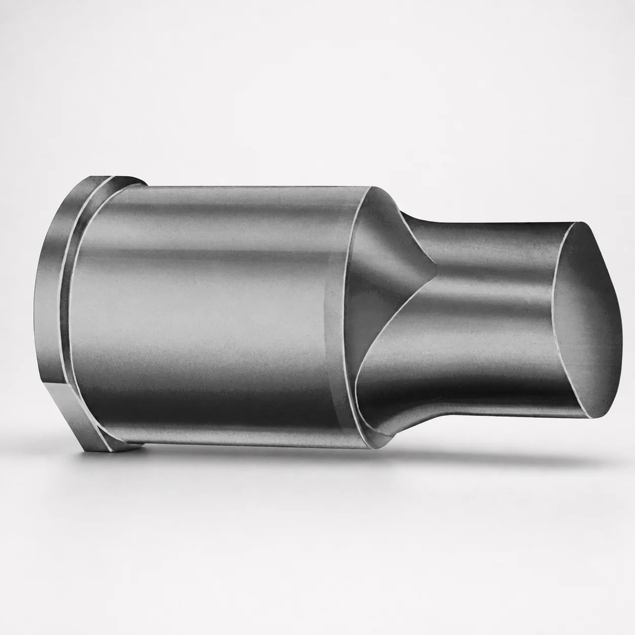
Extended Range Punches Metric X Tip
Extended Range Punches Metric X Tip are designed for stable, long-travel punch performance in progressive and forming dies. The X-shaped tip geometry helps deliver consistent material engagement while maintaining reliable positioning.
- Extended range punch body for controlled stroke and repeatable forming
- Durable, hardened tool construction supports long service life under load
- Manufactured for tight assembly compatibility with standard die sets
- Metric tooling option suited to punch/die maintenance and replacement programs
Specifications
50 configurations available
| Tip shape | D (Shank dia.) (mm) | L1 (Point Length) (mm) | L (Length) (mm) | P Dimension (mm) | W Dimension (mm) | R Dimension (mm) |
|---|---|---|---|---|---|---|
| H | 40 | 25 ~ 30 | 63 ~ 100 | 20 ~ 39.95 | 8 ~ 39.95 | - |
| H | 45 | 25 ~ 30 | 63 ~ 100 | 25 ~ 44.95 | 9 ~ 44.95 | - |
| H | 50 | 25 ~ 30 | 63 ~ 100 | 30 ~ 49.95 | 10 ~ 49.95 | - |
| H | 56 | 25 ~ 30 | 63 ~ 100 | 35 ~ 55.95 | 11 ~ 55.95 | - |
| H | 63 | 25 ~ 30 | 63 ~ 100 | 40 ~ 62.95 | 12 ~ 62.95 | - |
| J | 40 | 25 ~ 30 | 63 ~ 100 | 20 ~ 39.95 | 8 ~ 39.95 | - |
| J | 45 | 25 ~ 30 | 63 ~ 100 | 25 ~ 44.95 | 9 ~ 44.95 | - |
| J | 50 | 25 ~ 30 | 63 ~ 100 | 30 ~ 49.95 | 10 ~ 49.95 | - |
| J | 56 | 25 ~ 30 | 63 ~ 100 | 35 ~ 55.95 | 11 ~ 55.95 | - |
| J | 63 | 25 ~ 30 | 63 ~ 100 | 40 ~ 62.95 | 12 ~ 62.95 | - |
| K | 40 | 25 ~ 30 | 63 ~ 100 | 20 ~ 39.95 | 8 ~ 39.95 | 0.2 ~ 19.975 |
| K | 45 | 25 ~ 30 | 63 ~ 100 | 25 ~ 44.95 | 9 ~ 44.95 | 0.2 ~ 22.475 |
| K | 50 | 25 ~ 30 | 63 ~ 100 | 30 ~ 49.95 | 10 ~ 49.95 | 0.2 ~ 24.975 |
| K | 56 | 25 ~ 30 | 63 ~ 100 | 35 ~ 55.95 | 11 ~ 55.95 | 0.2 ~ 27.975 |
| K | 63 | 25 ~ 30 | 63 ~ 100 | 40 ~ 62.95 | 12 ~ 62.95 | 0.2 ~ 31.475 |
| N | 40 | 25 ~ 30 | 63 ~ 100 | - | 8 ~ 39.95 | - |
| N | 45 | 25 ~ 30 | 63 ~ 100 | - | 9 ~ 44.95 | - |
| N | 50 | 25 ~ 30 | 63 ~ 100 | - | 10 ~ 49.95 | - |
| N | 56 | 25 ~ 30 | 63 ~ 100 | - | 11 ~ 55.95 | - |
| N | 63 | 25 ~ 30 | 63 ~ 100 | - | 12 ~ 62.95 | - |
| O | 40 | 25 ~ 30 | 63 ~ 100 | 20 ~ 39.95 | 8 ~ 39.95 | - |
| O | 45 | 25 ~ 30 | 63 ~ 100 | 25 ~ 44.95 | 9 ~ 44.95 | - |
| O | 50 | 25 ~ 30 | 63 ~ 100 | 30 ~ 49.95 | 10 ~ 49.95 | - |
| O | 56 | 25 ~ 30 | 63 ~ 100 | 35 ~ 55.95 | 11 ~ 55.95 | - |
| O | 63 | 25 ~ 30 | 63 ~ 100 | 40 ~ 62.95 | 12 ~ 62.95 | - |
| R | 40 | 25 ~ 30 | 63 ~ 100 | 20 ~ 39.95 | 8 ~ 39.95 | - |
| R | 45 | 25 ~ 30 | 63 ~ 100 | 25 ~ 44.95 | 9 ~ 44.95 | - |
| R | 50 | 25 ~ 30 | 63 ~ 100 | 30 ~ 49.95 | 10 ~ 49.95 | - |
| R | 56 | 25 ~ 30 | 63 ~ 100 | 35 ~ 55.95 | 11 ~ 55.95 | - |
| R | 63 | 25 ~ 30 | 63 ~ 100 | 40 ~ 62.95 | 12 ~ 62.95 | - |
| V | 40 | 25 ~ 30 | 63 ~ 100 | 20 ~ 39.95 | 8 ~ 39.95 | - |
| V | 45 | 25 ~ 30 | 63 ~ 100 | 25 ~ 44.95 | 9 ~ 44.95 | - |
| V | 50 | 25 ~ 30 | 63 ~ 100 | 30 ~ 49.95 | 10 ~ 49.95 | - |
| V | 56 | 25 ~ 30 | 63 ~ 100 | 35 ~ 55.95 | 11 ~ 55.95 | - |
| V | 63 | 25 ~ 30 | 63 ~ 100 | 40 ~ 62.95 | 12 ~ 62.95 | - |
| X | 40 | 25 ~ 30 | 63 ~ 100 | 20 ~ 39.95 | - | - |
| X | 45 | 25 ~ 30 | 63 ~ 100 | 25 ~ 44.95 | - | - |
| X | 50 | 25 ~ 30 | 63 ~ 100 | 30 ~ 49.95 | - | - |
| X | 56 | 25 ~ 30 | 63 ~ 100 | 35 ~ 55.95 | - | - |
| X | 63 | 25 ~ 30 | 63 ~ 100 | 40 ~ 62.95 | - | - |
| Y | 40 | 25 ~ 30 | 63 ~ 100 | 20 ~ 39.95 | 8 ~ 39.95 | 0.2 ~ 19.975 |
| Y | 45 | 25 ~ 30 | 63 ~ 100 | 25 ~ 44.95 | 9 ~ 44.95 | 0.2 ~ 22.475 |
| Y | 50 | 25 ~ 30 | 63 ~ 100 | 30 ~ 49.95 | 10 ~ 49.95 | 0.2 ~ 24.975 |
| Y | 56 | 25 ~ 30 | 63 ~ 100 | 35 ~ 55.95 | 11 ~ 55.95 | 0.2 ~ 27.975 |
| Y | 63 | 25 ~ 30 | 63 ~ 100 | 40 ~ 62.95 | 12 ~ 62.95 | 0.2 ~ 31.475 |
| Z | 40 | 25 ~ 30 | 63 ~ 100 | - | 8 ~ 39.95 | 0.2 ~ 19.975 |
| Z | 45 | 25 ~ 30 | 63 ~ 100 | - | 9 ~ 44.95 | 0.2 ~ 22.475 |
| Z | 50 | 25 ~ 30 | 63 ~ 100 | - | 10 ~ 49.95 | 0.2 ~ 24.975 |
| Z | 56 | 25 ~ 30 | 63 ~ 100 | - | 11 ~ 55.95 | 0.2 ~ 27.975 |
| Z | 63 | 25 ~ 30 | 63 ~ 100 | - | 12 ~ 62.95 | 0.2 ~ 31.475 |
Product Guide
Application Scenarios+
This extended-range metric punch is used in progressive stamping and forming dies where the tooling must maintain stable engagement over a longer stroke. The extended body length helps control punch travel, supporting repeatable forming and consistent part geometry from cycle to cycle.
In automotive connector and bracket forming, punch wear and alignment directly affect hole size and burr formation. The X-tip geometry is suited for reliable material engagement, helping the punch maintain predictable cutting/forming action across the full travel.
For die and punch maintenance programs, this variant is designed as a metric option that supports compatibility with standard die sets, making it practical for replacement and tooling refurbishment without redesigning the entire tool block.
- Progressive forming: controlled long-travel stroke for stable output
- Stated tip shape (X) for consistent material engagement
- Metric tooling fit for maintenance-friendly die assembly
Material & Process Details+
The provided data focuses on dimensional and tip-geometry variants (tip shapes H, J, K, N, O, R, V, X, Y, Z). No specific steel grade, hardness (HRC), or heat-treatment state is included in the specifications, so those properties should be confirmed from your tooling purchase documentation or drawings for this exact DAYTON series.
In general, extended-range punches rely on hardened tool steels to balance wear resistance with toughness under bending and impact loads during stamping. Higher hardness typically improves edge life, while excessive hardness can reduce toughness and increase chipping risk.
- Confirm steel grade (e.g., SKD/H13 or equivalent) and heat treatment state (quench & temper, nitriding, etc.) from the product datasheet
- Hardness (HRC) and coating details should be verified per tip shape and diameter option
- Without grade confirmation, only dimensional suitability can be assured
Sizing & Selection Guide+
Select the punch by matching the shank diameter (D) and overall length (L) range to your die layout. The series offers D = 40, 45, 50, 56, 63 mm and L = 63 to 100 mm, which should be chosen to ensure proper guide engagement and sufficient exposure for the required stroke.
Then verify the working point size using L1 (point length) = 25 to 30 mm. This point length affects how much material is engaged and is critical for controlling forming depth and cut quality.
Finally, match the geometry parameters to your block clearances and alignment features:
- P options: 20 to 39.95, 25 to 44.95, 30 to 49.95, 35 to 55.95, 40 to 62.95 mm
- W options: 8 to 39.95, 9 to 44.95, 10 to 49.95, 11 to 55.95, 12 to 62.95 mm
- R options: 0.2 to 19.975, 0.2 to 22.475, 0.2 to 24.975, 0.2 to 27.975, 0.2 to 31.475 mm
Tip shape (including X) must match the process requirement, while tolerances/fit should follow your die set drawing because no tolerance values are provided in the input data.
Frequently Asked Questions
Which shank diameter (D) options are available for this extended-range metric punch, and how do I choose the correct one for my die set?+
What tip geometry options are supported, and why would I select tip shape X instead of another shape?+
How do I select the correct overall length (L) and point length (L1) to match my required punch stroke and forming depth?+
The P, W, and R parameters show multiple ranges—are these fixed dimensions or selectable variants?+
What hardness (HRC) or steel grade does this DAYTON punch use for wear resistance?+
Related Products






Need Custom Specifications?
Our engineering team can help with custom configurations, material selection, and volume pricing.