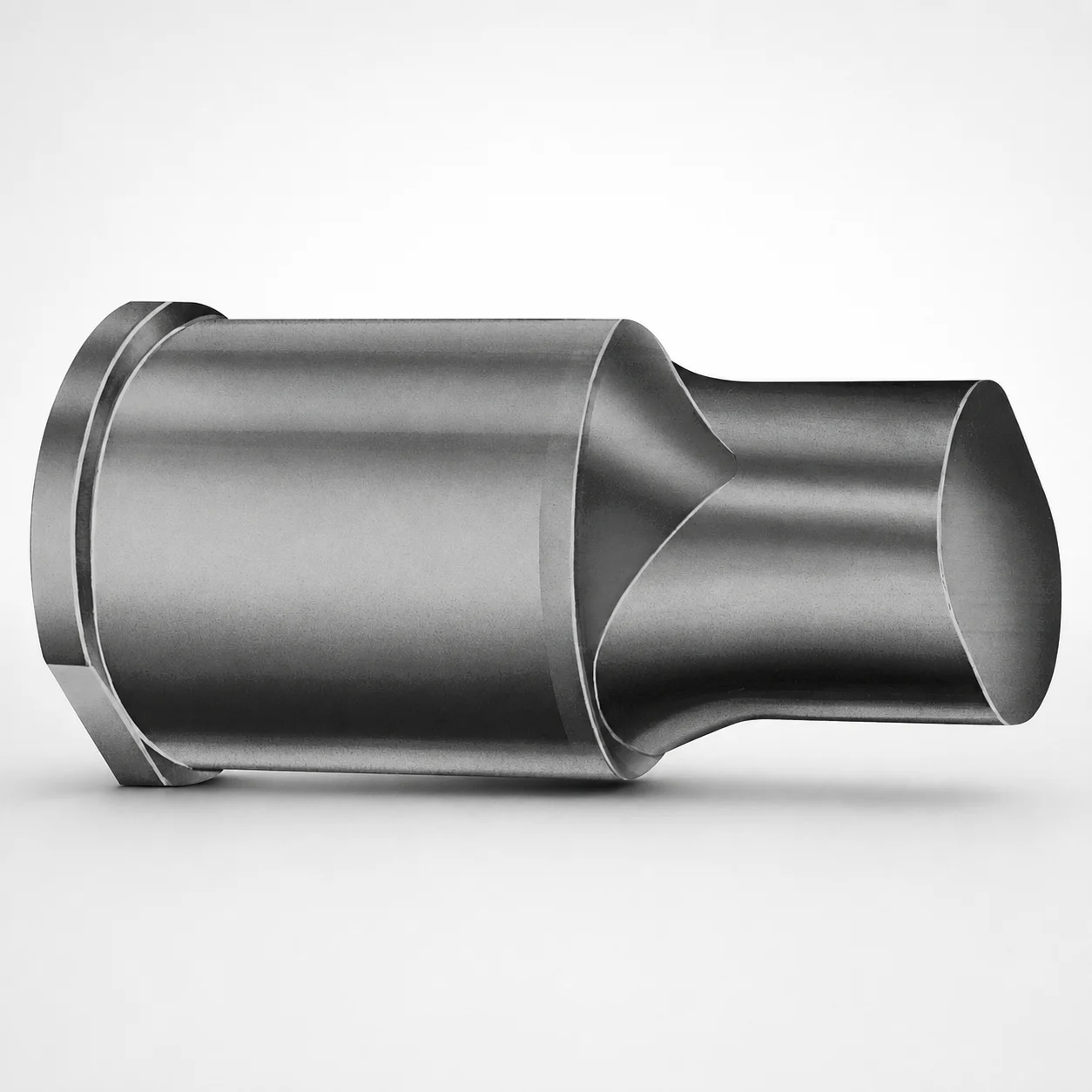
Extended Range Punches Metric X-Tip
Extended Range Punches Metric X-Tip (DAYTON) are precision punch components engineered for stable forming and repeatable tool alignment in press and die operations. The X-tip geometry supports controlled material contact for consistent cycle-to-cycle results.
- X-Tip punch profile for controlled engagement and consistent forming output
- Designed for durable performance under typical die wear conditions
- Extended range shank and overall lengths support flexible die design
- Built for metric punch applications in progressive and multi-station tooling
Specifications
50 configurations available
| Tip shape | D (Shank dia.) (mm) | L1 (Point Length) (mm) | L (Length) (mm) | P Dimension (mm) | W Dimension (mm) | R Dimension (mm) |
|---|---|---|---|---|---|---|
| H | 40 | 25 ~ 30 | 63 ~ 100 | 20 ~ 39.95 | 8 ~ 39.95 | - |
| H | 45 | 25 ~ 30 | 63 ~ 100 | 25 ~ 44.95 | 9 ~ 44.95 | - |
| H | 50 | 25 ~ 30 | 63 ~ 100 | 30 ~ 49.95 | 10 ~ 49.95 | - |
| H | 56 | 25 ~ 30 | 63 ~ 100 | 35 ~ 55.95 | 11 ~ 55.95 | - |
| H | 63 | 25 ~ 30 | 63 ~ 100 | 40 ~ 62.95 | 12 ~ 62.95 | - |
| J | 40 | 25 ~ 30 | 63 ~ 100 | 20 ~ 39.95 | 8 ~ 39.95 | - |
| J | 45 | 25 ~ 30 | 63 ~ 100 | 25 ~ 44.95 | 9 ~ 44.95 | - |
| J | 50 | 25 ~ 30 | 63 ~ 100 | 30 ~ 49.95 | 10 ~ 49.95 | - |
| J | 56 | 25 ~ 30 | 63 ~ 100 | 35 ~ 55.95 | 11 ~ 55.95 | - |
| J | 63 | 25 ~ 30 | 63 ~ 100 | 40 ~ 62.95 | 12 ~ 62.95 | - |
| K | 40 | 25 ~ 30 | 63 ~ 100 | 20 ~ 39.95 | 8 ~ 39.95 | 0.2 ~ 19.975 |
| K | 45 | 25 ~ 30 | 63 ~ 100 | 25 ~ 44.95 | 9 ~ 44.95 | 0.2 ~ 22.475 |
| K | 50 | 25 ~ 30 | 63 ~ 100 | 30 ~ 49.95 | 10 ~ 49.95 | 0.2 ~ 24.975 |
| K | 56 | 25 ~ 30 | 63 ~ 100 | 35 ~ 55.95 | 11 ~ 55.95 | 0.2 ~ 27.975 |
| K | 63 | 25 ~ 30 | 63 ~ 100 | 40 ~ 62.95 | 12 ~ 62.95 | 0.2 ~ 31.475 |
| N | 40 | 25 ~ 30 | 63 ~ 100 | - | 8 ~ 39.95 | - |
| N | 45 | 25 ~ 30 | 63 ~ 100 | - | 9 ~ 44.95 | - |
| N | 50 | 25 ~ 30 | 63 ~ 100 | - | 10 ~ 49.95 | - |
| N | 56 | 25 ~ 30 | 63 ~ 100 | - | 11 ~ 55.95 | - |
| N | 63 | 25 ~ 30 | 63 ~ 100 | - | 12 ~ 62.95 | - |
| O | 40 | 25 ~ 30 | 63 ~ 100 | 20 ~ 39.95 | 8 ~ 39.95 | - |
| O | 45 | 25 ~ 30 | 63 ~ 100 | 25 ~ 44.95 | 9 ~ 44.95 | - |
| O | 50 | 25 ~ 30 | 63 ~ 100 | 30 ~ 49.95 | 10 ~ 49.95 | - |
| O | 56 | 25 ~ 30 | 63 ~ 100 | 35 ~ 55.95 | 11 ~ 55.95 | - |
| O | 63 | 25 ~ 30 | 63 ~ 100 | 40 ~ 62.95 | 12 ~ 62.95 | - |
| R | 40 | 25 ~ 30 | 63 ~ 100 | 20 ~ 39.95 | 8 ~ 39.95 | - |
| R | 45 | 25 ~ 30 | 63 ~ 100 | 25 ~ 44.95 | 9 ~ 44.95 | - |
| R | 50 | 25 ~ 30 | 63 ~ 100 | 30 ~ 49.95 | 10 ~ 49.95 | - |
| R | 56 | 25 ~ 30 | 63 ~ 100 | 35 ~ 55.95 | 11 ~ 55.95 | - |
| R | 63 | 25 ~ 30 | 63 ~ 100 | 40 ~ 62.95 | 12 ~ 62.95 | - |
| V | 40 | 25 ~ 30 | 63 ~ 100 | 20 ~ 39.95 | 8 ~ 39.95 | - |
| V | 45 | 25 ~ 30 | 63 ~ 100 | 25 ~ 44.95 | 9 ~ 44.95 | - |
| V | 50 | 25 ~ 30 | 63 ~ 100 | 30 ~ 49.95 | 10 ~ 49.95 | - |
| V | 56 | 25 ~ 30 | 63 ~ 100 | 35 ~ 55.95 | 11 ~ 55.95 | - |
| V | 63 | 25 ~ 30 | 63 ~ 100 | 40 ~ 62.95 | 12 ~ 62.95 | - |
| X | 40 | 25 ~ 30 | 63 ~ 100 | 20 ~ 39.95 | - | - |
| X | 45 | 25 ~ 30 | 63 ~ 100 | 25 ~ 44.95 | - | - |
| X | 50 | 25 ~ 30 | 63 ~ 100 | 30 ~ 49.95 | - | - |
| X | 56 | 25 ~ 30 | 63 ~ 100 | 35 ~ 55.95 | - | - |
| X | 63 | 25 ~ 30 | 63 ~ 100 | 40 ~ 62.95 | - | - |
| Y | 40 | 25 ~ 30 | 63 ~ 100 | 20 ~ 39.95 | 8 ~ 39.95 | 0.2 ~ 19.975 |
| Y | 45 | 25 ~ 30 | 63 ~ 100 | 25 ~ 44.95 | 9 ~ 44.95 | 0.2 ~ 22.475 |
| Y | 50 | 25 ~ 30 | 63 ~ 100 | 30 ~ 49.95 | 10 ~ 49.95 | 0.2 ~ 24.975 |
| Y | 56 | 25 ~ 30 | 63 ~ 100 | 35 ~ 55.95 | 11 ~ 55.95 | 0.2 ~ 27.975 |
| Y | 63 | 25 ~ 30 | 63 ~ 100 | 40 ~ 62.95 | 12 ~ 62.95 | 0.2 ~ 31.475 |
| Z | 40 | 25 ~ 30 | 63 ~ 100 | - | 8 ~ 39.95 | 0.2 ~ 19.975 |
| Z | 45 | 25 ~ 30 | 63 ~ 100 | - | 9 ~ 44.95 | 0.2 ~ 22.475 |
| Z | 50 | 25 ~ 30 | 63 ~ 100 | - | 10 ~ 49.95 | 0.2 ~ 24.975 |
| Z | 56 | 25 ~ 30 | 63 ~ 100 | - | 11 ~ 55.95 | 0.2 ~ 27.975 |
| Z | 63 | 25 ~ 30 | 63 ~ 100 | - | 12 ~ 62.95 | 0.2 ~ 31.475 |
Product Guide
Application Scenarios+
Extended range standard punches are used in progressive and multi-station tooling where a punch must maintain consistent engagement across many cycles. The X-tip geometry helps create controlled material contact, supporting stable forming output and repeatable alignment during press runs.
- Automotive and appliance stamping: Apply these punches to pierce and form thin-to-medium stock in high-volume lines. The extended shank/overall length (L from 63–100 mm) supports flexible die layouts while the durable X-tip profile helps manage typical die wear.
- Electrical terminal and connector blanking: Use the available tip shapes (H, J, K, N, O, R, V, X, Y, Z) to match specific cut/blanking requirements. Matching point length L1 = 25–30 mm improves penetration consistency for repeatable part edges.
- General metal forming dies: For operations where tool-to-tool positioning must stay predictable, this variant’s design supports reliable alignment and controlled engagement under repeated strokes.
Material & Process Details+
The provided product data does not specify a steel grade, hardness (HRC), or heat-treatment state. As a result, material-property statements (e.g., quenched & tempered, nitrided, or a specific grade such as SKD61/H13) cannot be confirmed for this exact DAYTON series from the input.
For engineers selecting a punch steel, the typical trade-off is:
- Higher hardness steels improve wear resistance for long runs and abrasive die conditions.
- Higher toughness grades reduce chipping risk when forming loads fluctuate or when misalignment is present.
Manufacturing for punches in this category generally includes precision grinding of the tip profile and shank, with subsequent heat treatment tuned for the intended wear/toughness balance; confirm the actual spec sheet for this series before finalizing heat treatment and target hardness.
Sizing & Selection Guide+
Use the fixed and variable dimensions to match your punch penetration and die clearance needs. Start with L1 (point length) = 25–30 mm to ensure sufficient working length for the desired cut depth while maintaining safe support inside the die.
- Overall length L: Select L = 63–100 mm to fit your die stack-up and allow the required stick-out without interference.
- Shank diameter D: Choose from D = 40, 45, 50, 56, 63 mm to align with your guide bushing and punch holder bore dimensions.
- X-tip geometry: Pick the required tip shape (H, J, K, N, O, R, V, X, Y, Z) based on the part edge finish and forming mechanics.
For matching, pair the P and W dimensions (each provided as ranges for the configuration) with the corresponding die opening/relief geometry to control engagement. The R dimension (radii ranges from 0.2 mm up to 31.475 mm depending on variant) should be selected to suit the required corner radius at the cutting/forming interface. Tolerance and fit values are not provided here—verify the exact tolerance class for D and the holder interface in your receiving drawings.
Frequently Asked Questions
Which tip shapes (H/J/K/N/O/R/V/X/Y/Z) are suitable when I need different cut edge geometry in a progressive die?+
How do I choose the correct point length L1 for reliable penetration?+
What shank diameter D options are available, and how should they interface with punch guides/bushings?+
How do the P/W/R ranges help me match the punch geometry to the die cavity or opening?+
Can I use this extended range punch where my die stack requires longer overall length?+
Related Products






Need Custom Specifications?
Our engineering team can help with custom configurations, material selection, and volume pricing.