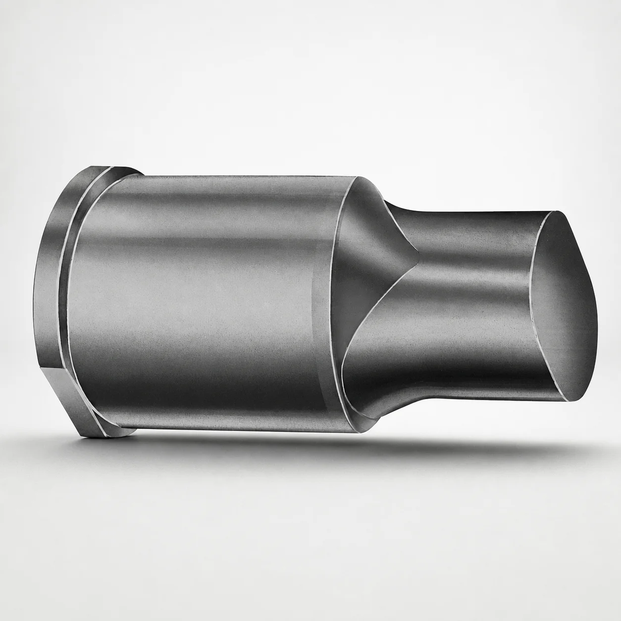
Metric Extended Range Punches with XCD Coating
Metric extended range punches with XCD coating are designed to deliver stable punching performance in deep or close-position die applications. The extended geometry supports consistent forming while the coating improves surface durability.
- Extended-range punch tip for reliable forming in deep die cavities
- XCD coating helps improve wear resistance during repeated cycles
- Built for metric tooling compatibility in standard punch-and-die setups
- Commonly used in progressive dies for precision blanking operations
Specifications
50 configurations available
| Tip shape | D (Shank dia.) (mm) | L1 (Point Length) (mm) | L (Length) (mm) | P Dimension (mm) | W Dimension (mm) | R Dimension (mm) |
|---|---|---|---|---|---|---|
| H | 40 | 25 ~ 30 | 63 ~ 100 | 20 ~ 39.95 | 8 ~ 39.95 | - |
| H | 45 | 25 ~ 30 | 63 ~ 100 | 25 ~ 44.95 | 9 ~ 44.95 | - |
| H | 50 | 25 ~ 30 | 63 ~ 100 | 30 ~ 49.95 | 10 ~ 49.95 | - |
| H | 56 | 25 ~ 30 | 63 ~ 100 | 35 ~ 55.95 | 11 ~ 55.95 | - |
| H | 63 | 25 ~ 30 | 63 ~ 100 | 40 ~ 62.95 | 12 ~ 62.95 | - |
| J | 40 | 25 ~ 30 | 63 ~ 100 | 20 ~ 39.95 | 8 ~ 39.95 | - |
| J | 45 | 25 ~ 30 | 63 ~ 100 | 25 ~ 44.95 | 9 ~ 44.95 | - |
| J | 50 | 25 ~ 30 | 63 ~ 100 | 30 ~ 49.95 | 10 ~ 49.95 | - |
| J | 56 | 25 ~ 30 | 63 ~ 100 | 35 ~ 55.95 | 11 ~ 55.95 | - |
| J | 63 | 25 ~ 30 | 63 ~ 100 | 40 ~ 62.95 | 12 ~ 62.95 | - |
| K | 40 | 25 ~ 30 | 63 ~ 100 | 20 ~ 39.95 | 8 ~ 39.95 | 0.2 ~ 19.975 |
| K | 45 | 25 ~ 30 | 63 ~ 100 | 25 ~ 44.95 | 9 ~ 44.95 | 0.2 ~ 22.475 |
| K | 50 | 25 ~ 30 | 63 ~ 100 | 30 ~ 49.95 | 10 ~ 49.95 | 0.2 ~ 24.975 |
| K | 56 | 25 ~ 30 | 63 ~ 100 | 35 ~ 55.95 | 11 ~ 55.95 | 0.2 ~ 27.975 |
| K | 63 | 25 ~ 30 | 63 ~ 100 | 40 ~ 62.95 | 12 ~ 62.95 | 0.2 ~ 31.475 |
| N | 40 | 25 ~ 30 | 63 ~ 100 | - | 8 ~ 39.95 | - |
| N | 45 | 25 ~ 30 | 63 ~ 100 | - | 9 ~ 44.95 | - |
| N | 50 | 25 ~ 30 | 63 ~ 100 | - | 10 ~ 49.95 | - |
| N | 56 | 25 ~ 30 | 63 ~ 100 | - | 11 ~ 55.95 | - |
| N | 63 | 25 ~ 30 | 63 ~ 100 | - | 12 ~ 62.95 | - |
| O | 40 | 25 ~ 30 | 63 ~ 100 | 20 ~ 39.95 | 8 ~ 39.95 | - |
| O | 45 | 25 ~ 30 | 63 ~ 100 | 25 ~ 44.95 | 9 ~ 44.95 | - |
| O | 50 | 25 ~ 30 | 63 ~ 100 | 30 ~ 49.95 | 10 ~ 49.95 | - |
| O | 56 | 25 ~ 30 | 63 ~ 100 | 35 ~ 55.95 | 11 ~ 55.95 | - |
| O | 63 | 25 ~ 30 | 63 ~ 100 | 40 ~ 62.95 | 12 ~ 62.95 | - |
| R | 40 | 25 ~ 30 | 63 ~ 100 | 20 ~ 39.95 | 8 ~ 39.95 | - |
| R | 45 | 25 ~ 30 | 63 ~ 100 | 25 ~ 44.95 | 9 ~ 44.95 | - |
| R | 50 | 25 ~ 30 | 63 ~ 100 | 30 ~ 49.95 | 10 ~ 49.95 | - |
| R | 56 | 25 ~ 30 | 63 ~ 100 | 35 ~ 55.95 | 11 ~ 55.95 | - |
| R | 63 | 25 ~ 30 | 63 ~ 100 | 40 ~ 62.95 | 12 ~ 62.95 | - |
| V | 40 | 25 ~ 30 | 63 ~ 100 | 20 ~ 39.95 | 8 ~ 39.95 | - |
| V | 45 | 25 ~ 30 | 63 ~ 100 | 25 ~ 44.95 | 9 ~ 44.95 | - |
| V | 50 | 25 ~ 30 | 63 ~ 100 | 30 ~ 49.95 | 10 ~ 49.95 | - |
| V | 56 | 25 ~ 30 | 63 ~ 100 | 35 ~ 55.95 | 11 ~ 55.95 | - |
| V | 63 | 25 ~ 30 | 63 ~ 100 | 40 ~ 62.95 | 12 ~ 62.95 | - |
| X | 40 | 25 ~ 30 | 63 ~ 100 | 20 ~ 39.95 | - | - |
| X | 45 | 25 ~ 30 | 63 ~ 100 | 25 ~ 44.95 | - | - |
| X | 50 | 25 ~ 30 | 63 ~ 100 | 30 ~ 49.95 | - | - |
| X | 56 | 25 ~ 30 | 63 ~ 100 | 35 ~ 55.95 | - | - |
| X | 63 | 25 ~ 30 | 63 ~ 100 | 40 ~ 62.95 | - | - |
| Y | 40 | 25 ~ 30 | 63 ~ 100 | 20 ~ 39.95 | 8 ~ 39.95 | 0.2 ~ 19.975 |
| Y | 45 | 25 ~ 30 | 63 ~ 100 | 25 ~ 44.95 | 9 ~ 44.95 | 0.2 ~ 22.475 |
| Y | 50 | 25 ~ 30 | 63 ~ 100 | 30 ~ 49.95 | 10 ~ 49.95 | 0.2 ~ 24.975 |
| Y | 56 | 25 ~ 30 | 63 ~ 100 | 35 ~ 55.95 | 11 ~ 55.95 | 0.2 ~ 27.975 |
| Y | 63 | 25 ~ 30 | 63 ~ 100 | 40 ~ 62.95 | 12 ~ 62.95 | 0.2 ~ 31.475 |
| Z | 40 | 25 ~ 30 | 63 ~ 100 | - | 8 ~ 39.95 | 0.2 ~ 19.975 |
| Z | 45 | 25 ~ 30 | 63 ~ 100 | - | 9 ~ 44.95 | 0.2 ~ 22.475 |
| Z | 50 | 25 ~ 30 | 63 ~ 100 | - | 10 ~ 49.95 | 0.2 ~ 24.975 |
| Z | 56 | 25 ~ 30 | 63 ~ 100 | - | 11 ~ 55.95 | 0.2 ~ 27.975 |
| Z | 63 | 25 ~ 30 | 63 ~ 100 | - | 12 ~ 62.95 | 0.2 ~ 31.475 |
Product Guide
Application Scenarios+
Metric extended-range punches are used in progressive die sets and fixture tooling when the punch must reach into deep or close-position die cavities while maintaining stable alignment and consistent penetration.
- Automotive and appliance progressive blanking: install in standard punch-and-die stations where repeated cycles demand surface durability; the extended point length (L1 25–30 mm) supports reliable material forming at depth.
- Connector/tab and small-part piercing: use the geometry options (H, J, K, N, O, R, V, X, Y, Z) to match the blanking feature and reduce variance at the punch interface during high-throughput production.
- Close-position forming in fixtures: the longer overall length (L 63–100 mm) helps reach constrained cavity depths, while XCD coating improves wear resistance for long runs.
This variant is suited to these applications because it combines extended geometry for deep access with an XCD coating that helps maintain punch surface condition under repeated punching loads.
Material & Process Details+
The input data specifies the tool geometry and XCD coating but does not provide the underlying punch steel grade, hardness, or heat treatment state. For coating selection and performance planning, the key material-related feature here is the XCD coating, which is intended to enhance wear resistance during repeated punching cycles.
- Coating effect: improves surface durability to help stabilize punch wear behavior in progressive dies.
- Trade-offs: with coated punches, long-run wear resistance is typically prioritized; however, ultimate toughness and resistance to chipping still depend on the base steel grade and quench/temper or nitriding process (not specified in the provided data).
- Material comparison: since multiple base steels are not listed, you should confirm the exact substrate grade and target hardness with the supplier before finalizing design life calculations.
If you share the steel grade and heat-treat/hardness data for this series, we can map it to common equivalents (e.g., H13/AISI 1.2344, M2/AISI 1.2070) and refine the hardness vs. toughness guidance.
Sizing & Selection Guide+
Select the extended punch dimensions by matching the cavity/core clearance and required reach for your progressive station or fixture.
- Choose overall reach: use L (63–100 mm) to ensure the punch extends far enough into deep or close-position die cavities without bottoming out.
- Match working point depth: set L1 (25–30 mm) to your required penetration/blanking depth so forming occurs consistently at the target location.
- Select the shank diameter: choose D (40, 45, 50, 56, 63 mm) based on the guide land and bushing compatibility for your press tooling.
- Confirm profile dimensions: align P, W, and R ranges to the mating die-opening geometry and punch/edge shape requirements. Available ranges include P = 20–39.95, 25–44.95, 30–49.95, 35–55.95, 40–62.95 mm; W = 8–39.95, 9–44.95, 10–49.95, 11–55.95, 12–62.95 mm; R = 0.2–19.975, 0.2–22.475, 0.2–24.975, 0.2–27.975, 0.2–31.475 mm.
Because the data provides dimension ranges rather than fixed values, treat these as configurable options—your final drawing should specify the exact P/W/R and the corresponding tip shape (H, J, K, N, O, R, V, X, Y, Z). Verify fit/clearance with your guide set and die opening tolerances, especially where the punch shank diameter D must run within its guide land limits.
Frequently Asked Questions
Which dimension primarily controls punch reach for deep or close-position die stations?+
How do I select the correct shank diameter (D) for compatibility with my guide set?+
What tip shape options are available and how should they be chosen for the die opening geometry?+
What do the P, W, and R dimension ranges mean for selecting the punch profile?+
Does the XCD coating change sizing or tolerance requirements versus uncoated punches?+
Related Products






Need Custom Specifications?
Our engineering team can help with custom configurations, material selection, and volume pricing.