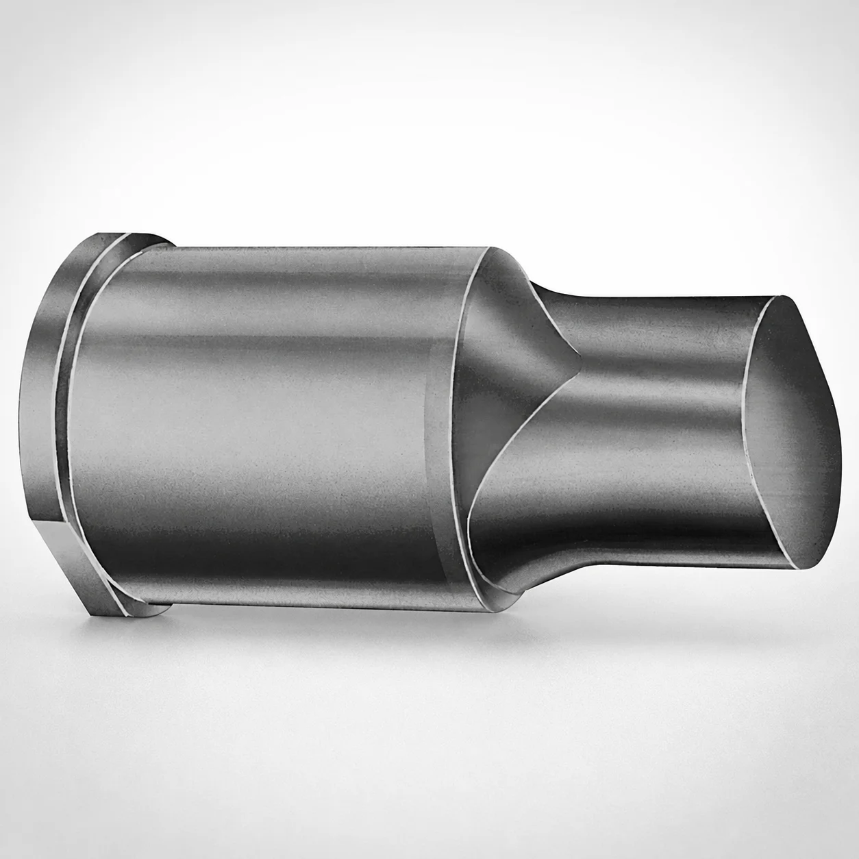
Extended Range Punches - Metric, XNP Coating
Extended range punches - metric, XNP coating (X-tip) are designed for long reach piercing in progressive and transfer dies. The extended cutting point helps maintain alignment during repeated forming cycles.
- X-tip geometry supports controlled penetration for consistent punch performance
- XNP coating improves wear resistance for hardened die steel applications
- Extended point and shank lengths reduce stack-up sensitivity in long-stroke tooling
- Built for metric punch-and-die sets in automotive, appliance, and industrial fabrication
Specifications
50 configurations available
| Tip shape | D (Shank dia.) (mm) | L1 (Point Length) (mm) | L (Length) (mm) | P Dimension (mm) | W Dimension (mm) | R Dimension (mm) |
|---|---|---|---|---|---|---|
| H | 40 | 25 ~ 30 | 63 ~ 100 | 20 ~ 39.95 | 8 ~ 39.95 | - |
| H | 45 | 25 ~ 30 | 63 ~ 100 | 25 ~ 44.95 | 9 ~ 44.95 | - |
| H | 50 | 25 ~ 30 | 63 ~ 100 | 30 ~ 49.95 | 10 ~ 49.95 | - |
| H | 56 | 25 ~ 30 | 63 ~ 100 | 35 ~ 55.95 | 11 ~ 55.95 | - |
| H | 63 | 25 ~ 30 | 63 ~ 100 | 40 ~ 62.95 | 12 ~ 62.95 | - |
| J | 40 | 25 ~ 30 | 63 ~ 100 | 20 ~ 39.95 | 8 ~ 39.95 | - |
| J | 45 | 25 ~ 30 | 63 ~ 100 | 25 ~ 44.95 | 9 ~ 44.95 | - |
| J | 50 | 25 ~ 30 | 63 ~ 100 | 30 ~ 49.95 | 10 ~ 49.95 | - |
| J | 56 | 25 ~ 30 | 63 ~ 100 | 35 ~ 55.95 | 11 ~ 55.95 | - |
| J | 63 | 25 ~ 30 | 63 ~ 100 | 40 ~ 62.95 | 12 ~ 62.95 | - |
| K | 40 | 25 ~ 30 | 63 ~ 100 | 20 ~ 39.95 | 8 ~ 39.95 | 0.2 ~ 19.975 |
| K | 45 | 25 ~ 30 | 63 ~ 100 | 25 ~ 44.95 | 9 ~ 44.95 | 0.2 ~ 22.475 |
| K | 50 | 25 ~ 30 | 63 ~ 100 | 30 ~ 49.95 | 10 ~ 49.95 | 0.2 ~ 24.975 |
| K | 56 | 25 ~ 30 | 63 ~ 100 | 35 ~ 55.95 | 11 ~ 55.95 | 0.2 ~ 27.975 |
| K | 63 | 25 ~ 30 | 63 ~ 100 | 40 ~ 62.95 | 12 ~ 62.95 | 0.2 ~ 31.475 |
| N | 40 | 25 ~ 30 | 63 ~ 100 | - | 8 ~ 39.95 | - |
| N | 45 | 25 ~ 30 | 63 ~ 100 | - | 9 ~ 44.95 | - |
| N | 50 | 25 ~ 30 | 63 ~ 100 | - | 10 ~ 49.95 | - |
| N | 56 | 25 ~ 30 | 63 ~ 100 | - | 11 ~ 55.95 | - |
| N | 63 | 25 ~ 30 | 63 ~ 100 | - | 12 ~ 62.95 | - |
| O | 40 | 25 ~ 30 | 63 ~ 100 | 20 ~ 39.95 | 8 ~ 39.95 | - |
| O | 45 | 25 ~ 30 | 63 ~ 100 | 25 ~ 44.95 | 9 ~ 44.95 | - |
| O | 50 | 25 ~ 30 | 63 ~ 100 | 30 ~ 49.95 | 10 ~ 49.95 | - |
| O | 56 | 25 ~ 30 | 63 ~ 100 | 35 ~ 55.95 | 11 ~ 55.95 | - |
| O | 63 | 25 ~ 30 | 63 ~ 100 | 40 ~ 62.95 | 12 ~ 62.95 | - |
| R | 40 | 25 ~ 30 | 63 ~ 100 | 20 ~ 39.95 | 8 ~ 39.95 | - |
| R | 45 | 25 ~ 30 | 63 ~ 100 | 25 ~ 44.95 | 9 ~ 44.95 | - |
| R | 50 | 25 ~ 30 | 63 ~ 100 | 30 ~ 49.95 | 10 ~ 49.95 | - |
| R | 56 | 25 ~ 30 | 63 ~ 100 | 35 ~ 55.95 | 11 ~ 55.95 | - |
| R | 63 | 25 ~ 30 | 63 ~ 100 | 40 ~ 62.95 | 12 ~ 62.95 | - |
| V | 40 | 25 ~ 30 | 63 ~ 100 | 20 ~ 39.95 | 8 ~ 39.95 | - |
| V | 45 | 25 ~ 30 | 63 ~ 100 | 25 ~ 44.95 | 9 ~ 44.95 | - |
| V | 50 | 25 ~ 30 | 63 ~ 100 | 30 ~ 49.95 | 10 ~ 49.95 | - |
| V | 56 | 25 ~ 30 | 63 ~ 100 | 35 ~ 55.95 | 11 ~ 55.95 | - |
| V | 63 | 25 ~ 30 | 63 ~ 100 | 40 ~ 62.95 | 12 ~ 62.95 | - |
| X | 40 | 25 ~ 30 | 63 ~ 100 | 20 ~ 39.95 | - | - |
| X | 45 | 25 ~ 30 | 63 ~ 100 | 25 ~ 44.95 | - | - |
| X | 50 | 25 ~ 30 | 63 ~ 100 | 30 ~ 49.95 | - | - |
| X | 56 | 25 ~ 30 | 63 ~ 100 | 35 ~ 55.95 | - | - |
| X | 63 | 25 ~ 30 | 63 ~ 100 | 40 ~ 62.95 | - | - |
| Y | 40 | 25 ~ 30 | 63 ~ 100 | 20 ~ 39.95 | 8 ~ 39.95 | 0.2 ~ 19.975 |
| Y | 45 | 25 ~ 30 | 63 ~ 100 | 25 ~ 44.95 | 9 ~ 44.95 | 0.2 ~ 22.475 |
| Y | 50 | 25 ~ 30 | 63 ~ 100 | 30 ~ 49.95 | 10 ~ 49.95 | 0.2 ~ 24.975 |
| Y | 56 | 25 ~ 30 | 63 ~ 100 | 35 ~ 55.95 | 11 ~ 55.95 | 0.2 ~ 27.975 |
| Y | 63 | 25 ~ 30 | 63 ~ 100 | 40 ~ 62.95 | 12 ~ 62.95 | 0.2 ~ 31.475 |
| Z | 40 | 25 ~ 30 | 63 ~ 100 | - | 8 ~ 39.95 | 0.2 ~ 19.975 |
| Z | 45 | 25 ~ 30 | 63 ~ 100 | - | 9 ~ 44.95 | 0.2 ~ 22.475 |
| Z | 50 | 25 ~ 30 | 63 ~ 100 | - | 10 ~ 49.95 | 0.2 ~ 24.975 |
| Z | 56 | 25 ~ 30 | 63 ~ 100 | - | 11 ~ 55.95 | 0.2 ~ 27.975 |
| Z | 63 | 25 ~ 30 | 63 ~ 100 | - | 12 ~ 62.95 | 0.2 ~ 31.475 |
Product Guide
Application Scenarios+
Extended range punches are used in progressive and transfer injection mold tooling when a die station requires deep, stable piercing across a larger stack of features. The extended cutting point and long reach help maintain alignment during repeated forming cycles, which is critical where small misregistration can create flash or inconsistent part geometry.
- Automotive connector and bracket assemblies: suited for long-stroke tooling where the punch must penetrate reliably through multi-layer cavities while keeping a controlled penetration profile.
- Appliance and industrial housings: the extended point and shank lengths reduce stack-up sensitivity in deeper mold sections, supporting consistent performance over high shot counts.
- Complex transfer die inserts: the X-tip variant geometry supports controlled penetration, helping ensure uniform forming across stations that repeat the same cutting action.
Choose this configuration when your mold design needs deep reach, controlled penetration, and improved wear behavior through compatible punch-and-die steel assemblies.
Material & Process Details+
The provided metadata specifies the XNP coating rather than a base steel grade. In practice, XNP coatings are selected for improved wear resistance at the working interface of the punch, helping punch and die assemblies withstand abrasive contact and repeated piercing cycles.
- Coating role (XNP): supports longer service life by reducing wear on the cutting point and guiding surfaces under hardened tooling conditions.
- Heat treatment (typical for application fit): these punches are commonly used in tool steels that are hardened and tempered or otherwise brought to a stable cutting hardness before coating application; this improves toughness–wear balance for deep piercing.
- Trade-offs: higher hardness improves wear resistance but can reduce toughness if not tempered correctly; pairing the coating with the right base hardness helps maintain durability.
If you need exact HRC and the specific steel grade, provide the steel selection (e.g., the order-specific spec), as it is not included in the current input data.
Sizing & Selection Guide+
Use the listed ranges to match the punch to the mold’s required reach, cutting engagement, and clearing behavior. Start by selecting D (shank diameter) from 40, 45, 50, 56, or 63 mm, which should be compatible with your punch holder and guided support bore to prevent deflection during deep piercing.
- Cutting reach: confirm L1 (point length) = 25 to 30 mm and L (overall length) = 63 to 100 mm so the cutting point extends far enough into the cavity stack without bottoming out.
- Geometric compatibility: select the correct P dimension (20–39.95 / 25–44.95 / 30–49.95 / 35–55.95 / 40–62.95 mm) and W dimension (8–39.95 / 9–44.95 / 10–49.95 / 11–55.95 / 12–62.95 mm) based on your die opening and required contact envelope.
- X-tip shape: choose tip shape H, J, K, N, O, R, V, X, Y, Z to match the desired penetration and cutting profile.
- Edge radii: verify R = 0.2–19.975 up to 0.2–31.475 mm to control clearance and reduce stress concentration.
Tolerance/fit: use standard punch-and-holder fit practices and verify that your holder bore and guidance system can accommodate the selected D and the intended lateral load from deep piercing.
Frequently Asked Questions
Which X-tip shape (H, J, K, N, O, R, V, X, Y, Z) should I select for deep piercing in a progressive die?+
How do I ensure the punch reach is correct using L1 and L for a given mold cavity stack height?+
What should I match between the punch shank diameter D and my punch holder guidance?+
How do P, W, and R dimensions affect die opening engagement for XNP-coated extended punches?+
Does the XNP coating change how I should treat or harden the punch and die steels?+
Related Products






Need Custom Specifications?
Our engineering team can help with custom configurations, material selection, and volume pricing.