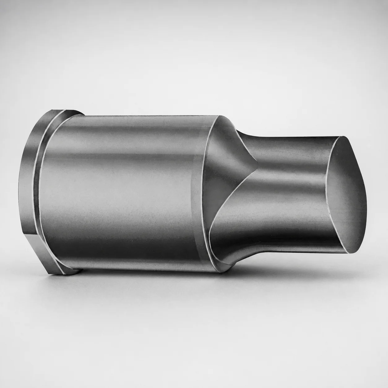
M2 Steel Extended Range Punches - Metric X Tip
Extended range punches - metric (M2 steel) with an X tip profile are designed for stable punching reach in tool and die production, helping maintain consistent part formation over repeated cycles.
- X tip geometry supports clean cutting action in confined layouts
- M2 steel construction with robust wear resistance for punch longevity
- Ground punch design supports repeatable alignment for consistent output
- Metric die making and press applications where extended reach is required
Specifications
100 configurations available
| Tip shape | Material | D (Shank dia.) (mm) | L1 (Point Length) (mm) | L (Length) (mm) | P Dimension (mm) | W Dimension (mm) | R Dimension (mm) |
|---|---|---|---|---|---|---|---|
| H | M2 | 40 | 25 ~ 30 | 63 ~ 100 | 20 ~ 39.95 | 8 ~ 39.95 | - |
| H | A2 | 40 | 25 ~ 30 | 63 ~ 100 | 20 ~ 39.95 | 8 ~ 39.95 | - |
| H | M2 | 45 | 25 ~ 30 | 63 ~ 100 | 25 ~ 44.95 | 9 ~ 44.95 | - |
| H | A2 | 45 | 25 ~ 30 | 63 ~ 100 | 25 ~ 44.95 | 9 ~ 44.95 | - |
| H | M2 | 50 | 25 ~ 30 | 63 ~ 100 | 30 ~ 49.95 | 10 ~ 49.95 | - |
| H | A2 | 50 | 25 ~ 30 | 63 ~ 100 | 30 ~ 49.95 | 10 ~ 49.95 | - |
| H | M2 | 56 | 25 ~ 30 | 63 ~ 100 | 35 ~ 55.95 | 11 ~ 55.95 | - |
| H | A2 | 56 | 25 ~ 30 | 63 ~ 100 | 35 ~ 55.95 | 11 ~ 55.95 | - |
| H | M2 | 63 | 25 ~ 30 | 63 ~ 100 | 40 ~ 62.95 | 12 ~ 62.95 | - |
| H | A2 | 63 | 25 ~ 30 | 63 ~ 100 | 40 ~ 62.95 | 12 ~ 62.95 | - |
| J | M2 | 40 | 25 ~ 30 | 63 ~ 100 | 20 ~ 39.95 | 8 ~ 39.95 | - |
| J | A2 | 40 | 25 ~ 30 | 63 ~ 100 | 20 ~ 39.95 | 8 ~ 39.95 | - |
| J | M2 | 45 | 25 ~ 30 | 63 ~ 100 | 25 ~ 44.95 | 9 ~ 44.95 | - |
| J | A2 | 45 | 25 ~ 30 | 63 ~ 100 | 25 ~ 44.95 | 9 ~ 44.95 | - |
| J | M2 | 50 | 25 ~ 30 | 63 ~ 100 | 30 ~ 49.95 | 10 ~ 49.95 | - |
| J | A2 | 50 | 25 ~ 30 | 63 ~ 100 | 30 ~ 49.95 | 10 ~ 49.95 | - |
| J | M2 | 56 | 25 ~ 30 | 63 ~ 100 | 35 ~ 55.95 | 11 ~ 55.95 | - |
| J | A2 | 56 | 25 ~ 30 | 63 ~ 100 | 35 ~ 55.95 | 11 ~ 55.95 | - |
| J | M2 | 63 | 25 ~ 30 | 63 ~ 100 | 40 ~ 62.95 | 12 ~ 62.95 | - |
| J | A2 | 63 | 25 ~ 30 | 63 ~ 100 | 40 ~ 62.95 | 12 ~ 62.95 | - |
| K | M2 | 40 | 25 ~ 30 | 63 ~ 100 | 20 ~ 39.95 | 8 ~ 39.95 | 0.2 ~ 19.975 |
| K | A2 | 40 | 25 ~ 30 | 63 ~ 100 | 20 ~ 39.95 | 8 ~ 39.95 | 0.2 ~ 19.975 |
| K | M2 | 45 | 25 ~ 30 | 63 ~ 100 | 25 ~ 44.95 | 9 ~ 44.95 | 0.2 ~ 22.475 |
| K | A2 | 45 | 25 ~ 30 | 63 ~ 100 | 25 ~ 44.95 | 9 ~ 44.95 | 0.2 ~ 22.475 |
| K | M2 | 50 | 25 ~ 30 | 63 ~ 100 | 30 ~ 49.95 | 10 ~ 49.95 | 0.2 ~ 24.975 |
| K | A2 | 50 | 25 ~ 30 | 63 ~ 100 | 30 ~ 49.95 | 10 ~ 49.95 | 0.2 ~ 24.975 |
| K | M2 | 56 | 25 ~ 30 | 63 ~ 100 | 35 ~ 55.95 | 11 ~ 55.95 | 0.2 ~ 27.975 |
| K | A2 | 56 | 25 ~ 30 | 63 ~ 100 | 35 ~ 55.95 | 11 ~ 55.95 | 0.2 ~ 27.975 |
| K | M2 | 63 | 25 ~ 30 | 63 ~ 100 | 40 ~ 62.95 | 12 ~ 62.95 | 0.2 ~ 31.475 |
| K | A2 | 63 | 25 ~ 30 | 63 ~ 100 | 40 ~ 62.95 | 12 ~ 62.95 | 0.2 ~ 31.475 |
| N | M2 | 40 | 25 ~ 30 | 63 ~ 100 | - | 8 ~ 39.95 | - |
| N | A2 | 40 | 25 ~ 30 | 63 ~ 100 | - | 8 ~ 39.95 | - |
| N | M2 | 45 | 25 ~ 30 | 63 ~ 100 | - | 9 ~ 44.95 | - |
| N | A2 | 45 | 25 ~ 30 | 63 ~ 100 | - | 9 ~ 44.95 | - |
| N | M2 | 50 | 25 ~ 30 | 63 ~ 100 | - | 10 ~ 49.95 | - |
| N | A2 | 50 | 25 ~ 30 | 63 ~ 100 | - | 10 ~ 49.95 | - |
| N | M2 | 56 | 25 ~ 30 | 63 ~ 100 | - | 11 ~ 55.95 | - |
| N | A2 | 56 | 25 ~ 30 | 63 ~ 100 | - | 11 ~ 55.95 | - |
| N | M2 | 63 | 25 ~ 30 | 63 ~ 100 | - | 12 ~ 62.95 | - |
| N | A2 | 63 | 25 ~ 30 | 63 ~ 100 | - | 12 ~ 62.95 | - |
| O | M2 | 40 | 25 ~ 30 | 63 ~ 100 | 20 ~ 39.95 | 8 ~ 39.95 | - |
| O | A2 | 40 | 25 ~ 30 | 63 ~ 100 | 20 ~ 39.95 | 8 ~ 39.95 | - |
| O | M2 | 45 | 25 ~ 30 | 63 ~ 100 | 25 ~ 44.95 | 9 ~ 44.95 | - |
| O | A2 | 45 | 25 ~ 30 | 63 ~ 100 | 25 ~ 44.95 | 9 ~ 44.95 | - |
| O | M2 | 50 | 25 ~ 30 | 63 ~ 100 | 30 ~ 49.95 | 10 ~ 49.95 | - |
| O | A2 | 50 | 25 ~ 30 | 63 ~ 100 | 30 ~ 49.95 | 10 ~ 49.95 | - |
| O | M2 | 56 | 25 ~ 30 | 63 ~ 100 | 35 ~ 55.95 | 11 ~ 55.95 | - |
| O | A2 | 56 | 25 ~ 30 | 63 ~ 100 | 35 ~ 55.95 | 11 ~ 55.95 | - |
| O | M2 | 63 | 25 ~ 30 | 63 ~ 100 | 40 ~ 62.95 | 12 ~ 62.95 | - |
| O | A2 | 63 | 25 ~ 30 | 63 ~ 100 | 40 ~ 62.95 | 12 ~ 62.95 | - |
Product Guide
Application Scenarios+
Extended reach punches with an X tip profile are commonly used in injection mold tooling where a punch must reach deeper into the die while maintaining clean shearing. The extended length range (L 63–100 mm) helps support stable punch penetration in tightly packaged cavity layouts.
- Automotive and appliance parting-line trims: Use the X tip geometry to promote a controlled cutting action when space is limited, reducing risk of edge deformation during repeated production cycles.
- Connector and bracket insert-hold operations: The punch’s reach supports accurate forming of features in metric tooling, especially where the cavity/core spacing demands longer actuation length.
- General production tool-and-die stations: M2-based construction offers the wear resistance expected for frequent punch use, supporting consistent part formation across long runs.
This variant is suited to metric die making due to the defined shank diameter options (D: 40–63 mm) and standardized point length (L1 25–30 mm), enabling reliable fit to punch plates and guides.
Material & Process Details+
This extended-range punch series is offered in M2 and A2 steels. M2 steel (high-speed steel class) is selected for wear resistance in production punching, helping maintain edge geometry under repetitive cutting loads. A2 is typically chosen when a balance of toughness and wear performance is needed, but its performance profile differs from M2 for high-wear applications.
For mold components like punches, the steel is commonly supplied in a heat-treated condition appropriate for cutting use, typically quenched and tempered for stable hardness before grinding to final dimensions. Final hardness is not provided in the supplied data; however, sizing and selection should assume a hardened cutting state suitable for punching wear rather than soft machining.
- Trade-off: Higher wear resistance steels help resist abrasion, while toughness determines how well the punch tolerates impact and load spikes.
- Manufacturing: Ground punch surfaces and precise tip geometry support repeatable alignment and clean cutting action.
Sizing & Selection Guide+
To select the correct extended-range punch, match the required shank diameter (D) and overall length to the tool cavity/core spacing and punch plate thickness. This series provides D = 40, 45, 50, 56, or 63 mm and a fixed point length (L1) of 25–30 mm.
Next, confirm the needed reach using the fixed overall length L = 63–100 mm. Choose the specific variant that provides the required engagement without bottoming out in the tool set, especially for deep feature forming.
- P dimension: select from 20–39.95, 25–44.95, 30–49.95, 35–55.95, or 40–62.95 mm depending on where the punch tip must position relative to the die.
- W dimension: choose from 8–39.95, 9–44.95, 10–49.95, 11–55.95, or 12–62.95 mm to align with pocket/clearance geometry.
- R dimension: verify radius compatibility using 0.2–31.475 mm ranges.
Because the P/W/R values are given as ranges, ensure your CAD drawing selects the exact variant that meets your cavity/core clearance and maintains the intended fit at assembly. When guide systems are used, keep clearance consistent with the punch shank diameter selection.
Frequently Asked Questions
Which tip shape options are available for these metric extended-range punches, and what is the impact of choosing the X profile?+
This series supports multiple tip shapes: H, J, K, N, O, R, V, X, Y, Z. The X tip profile is intended to support a controlled cutting action in confined tool layouts, which can help maintain feature formation during repeated cycles.
How do I choose between M2 and A2 steel for production wear in standard punch stations?+
The product is offered in M2 and A2 steels. The supplied description specifically highlights M2 steel for reliable punch wear resistance in production.
Use the intended steel selection based on your expected abrasion and cut-load conditions; if your process involves higher wear, M2 is the documented choice, while A2 is an alternative when you need a different balance of performance.
What are the fixed and variable dimensions I must verify when matching an extended-range punch to my die cavity/core spacing?+
Fixed dimensions in the provided specs are L1 = 25–30 mm (point length) and L = 63–100 mm (overall length). Variable dimensions include D = 40, 45, 50, 56, 63 mm plus P, W, and R ranges.
Match L to the required reach so the punch engages fully without bottoming, then verify D for shank fit in your punch plate and guides.
Which dimension ranges should I use to set the punch tip positioning and clearance in CAD/CAM?+
Tip positioning and clearance are controlled by the P and W dimensions (each provided as selectable ranges), along with the R radius options. Choose the variant whose P and W ranges align with the space between the punch tip and die surfaces in your model.
Confirm the required radius compatibility using R = 0.2–31.475 mm (depending on the specific variant option).
Are there configurable parameters (tip shape and material) in this series, or are dimensions fixed?+
Configuration is available for tip shape and material. Tip shape can be selected from H, J, K, N, O, R, V, X, Y, Z, and material from M2 or A2.
In contrast, L1 (25–30 mm) and L (63–100 mm) are fixed overall design constraints, while D, P, W, and R are specified by selectable ranges.
Related Products






Need Custom Specifications?
Our engineering team can help with custom configurations, material selection, and volume pricing.