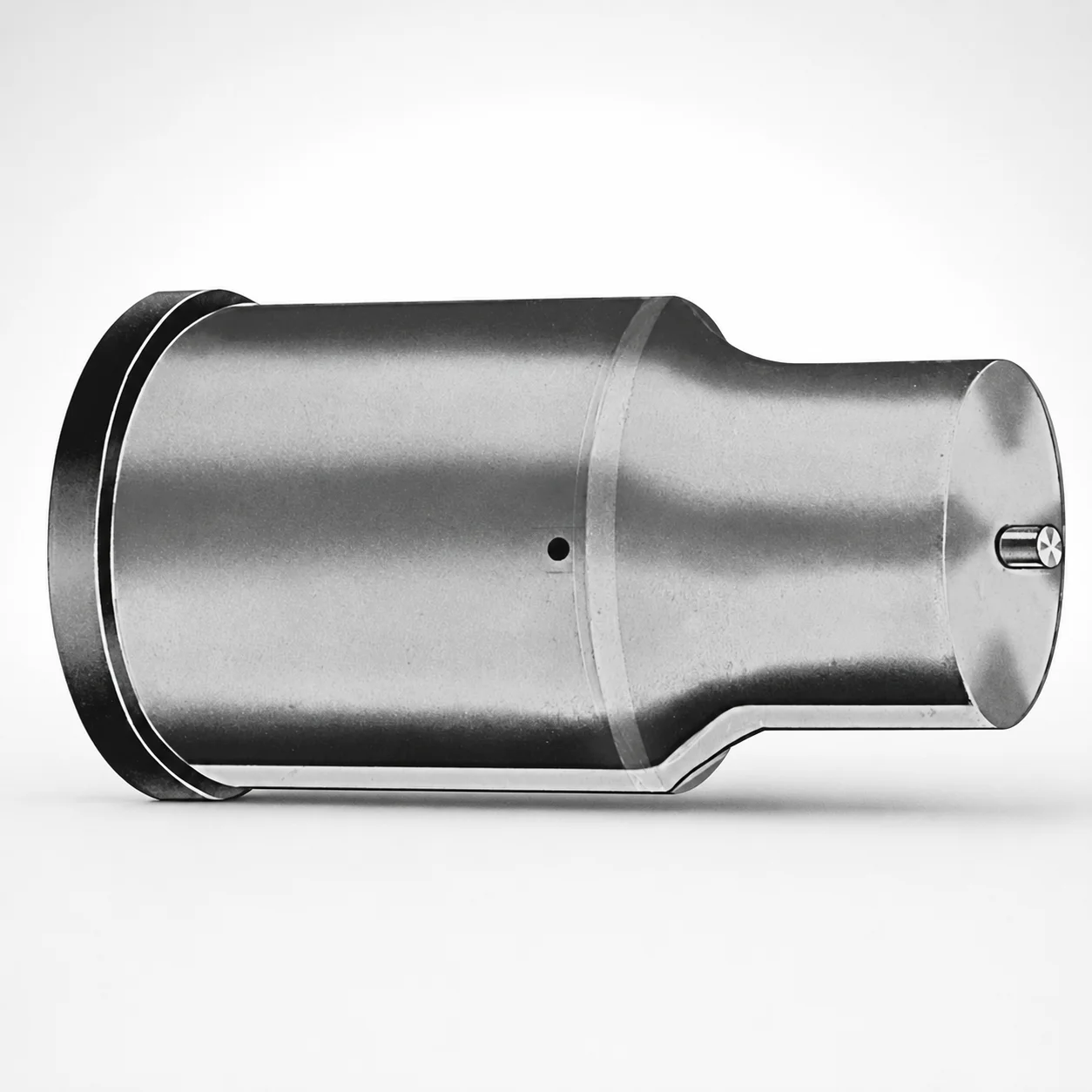
Extended Range Ejector Punches Metric XVP Coating
Extended Range Ejector Punches (Metric) with XVP coating are designed for reliable tool return and stable part ejection in demanding production cycles. The extended length helps reach deeper cavities while maintaining dimensional consistency.
- Extended punch geometry supports reach into deeper die cavities
- XVP coating enhances surface wear and reduces friction during operation
- Metric design maintains repeatable fit for efficient die assembly
- Suitable for precision punching and die insert applications
Specifications
50 configurations available
| Tip shape | D (Shank dia.) (mm) | L1 (Point Length) (mm) | L (Length) (mm) | P Dimension (mm) | W Dimension (mm) | R Dimension (mm) |
|---|---|---|---|---|---|---|
| H | 40 | 25 ~ 30 | 63 ~ 100 | 20 ~ 39.95 | 8 ~ 39.95 | - |
| H | 45 | 25 ~ 30 | 63 ~ 100 | 25 ~ 44.95 | 9 ~ 44.95 | - |
| H | 50 | 25 ~ 30 | 63 ~ 100 | 30 ~ 49.95 | 10 ~ 49.95 | - |
| H | 56 | 25 ~ 30 | 63 ~ 100 | 35 ~ 55.95 | 11 ~ 55.95 | - |
| H | 63 | 25 ~ 30 | 63 ~ 100 | 40 ~ 62.95 | 12 ~ 62.95 | - |
| J | 40 | 25 ~ 30 | 63 ~ 100 | 20 ~ 39.95 | 8 ~ 39.95 | - |
| J | 45 | 25 ~ 30 | 63 ~ 100 | 25 ~ 44.95 | 9 ~ 44.95 | - |
| J | 50 | 25 ~ 30 | 63 ~ 100 | 30 ~ 49.95 | 10 ~ 49.95 | - |
| J | 56 | 25 ~ 30 | 63 ~ 100 | 35 ~ 55.95 | 11 ~ 55.95 | - |
| J | 63 | 25 ~ 30 | 63 ~ 100 | 40 ~ 62.95 | 12 ~ 62.95 | - |
| K | 40 | 25 ~ 30 | 63 ~ 100 | 20 ~ 39.95 | 8 ~ 39.95 | 0.2 ~ 19.975 |
| K | 45 | 25 ~ 30 | 63 ~ 100 | 25 ~ 44.95 | 9 ~ 44.95 | 0.2 ~ 22.475 |
| K | 50 | 25 ~ 30 | 63 ~ 100 | 30 ~ 49.95 | 10 ~ 49.95 | 0.2 ~ 24.975 |
| K | 56 | 25 ~ 30 | 63 ~ 100 | 35 ~ 55.95 | 11 ~ 55.95 | 0.2 ~ 27.975 |
| K | 63 | 25 ~ 30 | 63 ~ 100 | 40 ~ 62.95 | 12 ~ 62.95 | 0.2 ~ 31.475 |
| N | 40 | 25 ~ 30 | 63 ~ 100 | - | 8 ~ 39.95 | - |
| N | 45 | 25 ~ 30 | 63 ~ 100 | - | 9 ~ 44.95 | - |
| N | 50 | 25 ~ 30 | 63 ~ 100 | - | 10 ~ 49.95 | - |
| N | 56 | 25 ~ 30 | 63 ~ 100 | - | 11 ~ 55.95 | - |
| N | 63 | 25 ~ 30 | 63 ~ 100 | - | 12 ~ 62.95 | - |
| O | 40 | 25 ~ 30 | 63 ~ 100 | 20 ~ 39.95 | 8 ~ 39.95 | - |
| O | 45 | 25 ~ 30 | 63 ~ 100 | 25 ~ 44.95 | 9 ~ 44.95 | - |
| O | 50 | 25 ~ 30 | 63 ~ 100 | 30 ~ 49.95 | 10 ~ 49.95 | - |
| O | 56 | 25 ~ 30 | 63 ~ 100 | 35 ~ 55.95 | 11 ~ 55.95 | - |
| O | 63 | 25 ~ 30 | 63 ~ 100 | 40 ~ 62.95 | 12 ~ 62.95 | - |
| R | 40 | 25 ~ 30 | 63 ~ 100 | 20 ~ 39.95 | 8 ~ 39.95 | - |
| R | 45 | 25 ~ 30 | 63 ~ 100 | 25 ~ 44.95 | 9 ~ 44.95 | - |
| R | 50 | 25 ~ 30 | 63 ~ 100 | 30 ~ 49.95 | 10 ~ 49.95 | - |
| R | 56 | 25 ~ 30 | 63 ~ 100 | 35 ~ 55.95 | 11 ~ 55.95 | - |
| R | 63 | 25 ~ 30 | 63 ~ 100 | 40 ~ 62.95 | 12 ~ 62.95 | - |
| V | 40 | 25 ~ 30 | 63 ~ 100 | 20 ~ 39.95 | 8 ~ 39.95 | - |
| V | 45 | 25 ~ 30 | 63 ~ 100 | 25 ~ 44.95 | 9 ~ 44.95 | - |
| V | 50 | 25 ~ 30 | 63 ~ 100 | 30 ~ 49.95 | 10 ~ 49.95 | - |
| V | 56 | 25 ~ 30 | 63 ~ 100 | 35 ~ 55.95 | 11 ~ 55.95 | - |
| V | 63 | 25 ~ 30 | 63 ~ 100 | 40 ~ 62.95 | 12 ~ 62.95 | - |
| X | 40 | 25 ~ 30 | 63 ~ 100 | 20 ~ 39.95 | - | - |
| X | 45 | 25 ~ 30 | 63 ~ 100 | 25 ~ 44.95 | - | - |
| X | 50 | 25 ~ 30 | 63 ~ 100 | 30 ~ 49.95 | - | - |
| X | 56 | 25 ~ 30 | 63 ~ 100 | 35 ~ 55.95 | - | - |
| X | 63 | 25 ~ 30 | 63 ~ 100 | 40 ~ 62.95 | - | - |
| Y | 40 | 25 ~ 30 | 63 ~ 100 | 20 ~ 39.95 | 8 ~ 39.95 | 0.2 ~ 19.975 |
| Y | 45 | 25 ~ 30 | 63 ~ 100 | 25 ~ 44.95 | 9 ~ 44.95 | 0.2 ~ 22.475 |
| Y | 50 | 25 ~ 30 | 63 ~ 100 | 30 ~ 49.95 | 10 ~ 49.95 | 0.2 ~ 24.975 |
| Y | 56 | 25 ~ 30 | 63 ~ 100 | 35 ~ 55.95 | 11 ~ 55.95 | 0.2 ~ 27.975 |
| Y | 63 | 25 ~ 30 | 63 ~ 100 | 40 ~ 62.95 | 12 ~ 62.95 | 0.2 ~ 31.475 |
| Z | 40 | 25 ~ 30 | 63 ~ 100 | - | 8 ~ 39.95 | 0.2 ~ 19.975 |
| Z | 45 | 25 ~ 30 | 63 ~ 100 | - | 9 ~ 44.95 | 0.2 ~ 22.475 |
| Z | 50 | 25 ~ 30 | 63 ~ 100 | - | 10 ~ 49.95 | 0.2 ~ 24.975 |
| Z | 56 | 25 ~ 30 | 63 ~ 100 | - | 11 ~ 55.95 | 0.2 ~ 27.975 |
| Z | 63 | 25 ~ 30 | 63 ~ 100 | - | 12 ~ 62.95 | 0.2 ~ 31.475 |
Product Guide
Application Scenarios+
Where it fits in: These metric extended ejector punches are used in injection molding and related tooling that requires stable part ejection from deeper cavities, such as core-side access designs and long-stroke ejection systems.
Scenario 1 — Automotive connector housings: In multi-cavity automotive connector molds, the extended length helps transmit ejection force to recessed gates and deep ribs without compromising punch alignment. The XVP coating supports smooth slide/return behavior and improved wear performance over high-cycle production.
Scenario 2 — Consumer electronics housings: For thin-wall housings with local undercuts, the selectable tip shapes (H/J/K/N/O/R/V/X/Y/Z) allow engineers to match the contact geometry to the part without damaging functional surfaces. The extended punch profile helps maintain dimensional consistency during repeated tool cycling.
Scenario 3 — Die casting or punching press tooling: When used as ejector/punch components in demanding press environments, the coating reduces friction and helps manage surface wear, improving tool return reliability and maintaining stable ejection over time.
- Extended geometry reaches deeper cavity features
- XVP coating improves wear resistance and reduces friction
- Metric dimensions support repeatable assembly and alignment
Material & Process Details+
The provided specifications describe the extended geometry and XVP coating, but no explicit base steel grade, hardness, or heat-treatment state is listed in the input data. Because of that, material-property claims such as exact HRC, specific wear coefficients, or “quenched & tempered to X” cannot be stated reliably here.
What can be qualified from the given info:
- XVP coating: intended to enhance surface wear resistance and reduce friction during punch/ejection cycling.
- Wear vs. toughness trade-off: surface-coating solutions typically improve tribology and reduce galling risk while relying on the underlying steel’s toughness for impact and bending resistance; selecting a suitable punch steel grade is still required for specific press loads.
- Heat treatment: the input does not specify pre-hardened, quenched & tempered, or nitrided condition, so the exact treatment should be confirmed from the supplier’s material certification for the same series.
If you share the base material/heat-treat documentation for series 250301827739, this section can be completed with the exact steel grade and target hardness.
Sizing & Selection Guide+
Step 1: Match reach — Select the overall length L = 63 ~ 100 mm so the punch tip can fully cover the deepest ejector contact point in your cavity/core stack-up. For the tip engagement zone, use the fixed point length L1 = 25 ~ 30 mm to ensure adequate contact while avoiding excessive protrusion.
Step 2: Select shank diameter — Choose D (shank dia.) = 40, 45, 50, 56, or 63 mm to fit your guide/bushing and maintain alignment. Larger D generally improves bending stiffness, which can matter in deep-cavity ejection.
Step 3: Choose contact geometry — Pick the required tip shape (H/J/K/N/O/R/V/X/Y/Z) and then match the P/W/R dimensions to your mating die insert geometry. The available ranges are P = 20 ~ 39.95, 25 ~ 44.95, 30 ~ 49.95, 35 ~ 55.95, 40 ~ 62.95; W = 8 ~ 39.95, 9 ~ 44.95, 10 ~ 49.95, 11 ~ 55.95, 12 ~ 62.95; and R = 0.2 ~ 19.975, 0.2 ~ 22.475, 0.2 ~ 24.975, 0.2 ~ 27.975, 0.2 ~ 31.475.
- Confirm clearance/fit against your guide bore and expected ejection stroke.
- Because tolerances are not provided in the input data, verify final fit using your engineering drawings and the supplier’s dimensional tolerances for this series.
- Tip shape and geometry are effectively configurable via the listed variable dimensions; L1 is fixed within 25 ~ 30 mm.
Frequently Asked Questions
Which tip shapes (H/J/K/N/O/R/V/X/Y/Z) are best for protecting surfaces in deep-cavity part ejection?+
How do I choose the correct overall length L (63–100 mm) and point length L1 (25–30 mm) for a deep cavity mold?+
What shank diameter D options are available, and how do they impact guide fit and stiffness?+
How should I match P, W, and R dimensions to an ejector/punch seat in the mold insert?+
What does the XVP coating contribute for high-cycle tooling compared with uncoated punches?+
Related Products






Need Custom Specifications?
Our engineering team can help with custom configurations, material selection, and volume pricing.