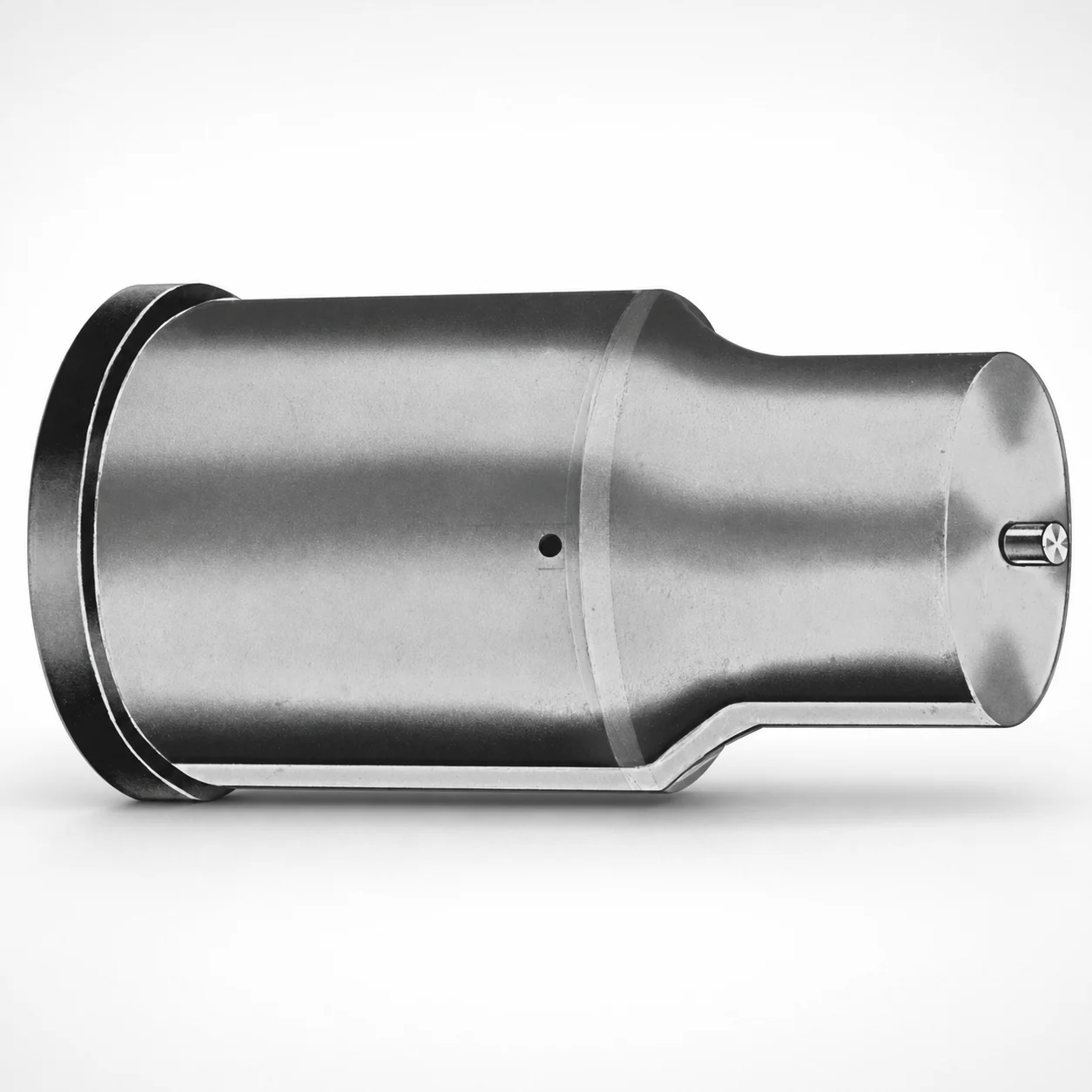
Extended Range Jector Punches Metric XNT DayTiN® Coating
Extended Range Jector Punches Metric (XNT DayTiN® coating) are designed for reliable ejection over longer stroke lengths, helping maintain stable punch guidance in production dies. The coated surface supports improved wear resistance and process consistency under repeated cycles.
- Extended reach design for stable punch travel in tight die layouts
- XNT DayTiN® coated surface improves wear resistance and reduces friction
- Available tip shapes (X, R, K, O, H, J, N, V, Y, Z) to match die geometry
- Metric punch use in progressive forming, trimming, and knockout stations
Specifications
50 configurations available
| Tip shape | D (Shank dia.) (mm) | L1 (Point Length) (mm) | L (Length) (mm) | P Dimension (mm) | W Dimension (mm) | R Dimension (mm) |
|---|---|---|---|---|---|---|
| H | 40 | 25 ~ 30 | 63 ~ 100 | 20 ~ 39.95 | 8 ~ 39.95 | - |
| H | 45 | 25 ~ 30 | 63 ~ 100 | 25 ~ 44.95 | 9 ~ 44.95 | - |
| H | 50 | 25 ~ 30 | 63 ~ 100 | 30 ~ 49.95 | 10 ~ 49.95 | - |
| H | 56 | 25 ~ 30 | 63 ~ 100 | 35 ~ 55.95 | 11 ~ 55.95 | - |
| H | 63 | 25 ~ 30 | 63 ~ 100 | 40 ~ 62.95 | 12 ~ 62.95 | - |
| J | 40 | 25 ~ 30 | 63 ~ 100 | 20 ~ 39.95 | 8 ~ 39.95 | - |
| J | 45 | 25 ~ 30 | 63 ~ 100 | 25 ~ 44.95 | 9 ~ 44.95 | - |
| J | 50 | 25 ~ 30 | 63 ~ 100 | 30 ~ 49.95 | 10 ~ 49.95 | - |
| J | 56 | 25 ~ 30 | 63 ~ 100 | 35 ~ 55.95 | 11 ~ 55.95 | - |
| J | 63 | 25 ~ 30 | 63 ~ 100 | 40 ~ 62.95 | 12 ~ 62.95 | - |
| K | 40 | 25 ~ 30 | 63 ~ 100 | 20 ~ 39.95 | 8 ~ 39.95 | 0.2 ~ 19.975 |
| K | 45 | 25 ~ 30 | 63 ~ 100 | 25 ~ 44.95 | 9 ~ 44.95 | 0.2 ~ 22.475 |
| K | 50 | 25 ~ 30 | 63 ~ 100 | 30 ~ 49.95 | 10 ~ 49.95 | 0.2 ~ 24.975 |
| K | 56 | 25 ~ 30 | 63 ~ 100 | 35 ~ 55.95 | 11 ~ 55.95 | 0.2 ~ 27.975 |
| K | 63 | 25 ~ 30 | 63 ~ 100 | 40 ~ 62.95 | 12 ~ 62.95 | 0.2 ~ 31.475 |
| N | 40 | 25 ~ 30 | 63 ~ 100 | - | 8 ~ 39.95 | - |
| N | 45 | 25 ~ 30 | 63 ~ 100 | - | 9 ~ 44.95 | - |
| N | 50 | 25 ~ 30 | 63 ~ 100 | - | 10 ~ 49.95 | - |
| N | 56 | 25 ~ 30 | 63 ~ 100 | - | 11 ~ 55.95 | - |
| N | 63 | 25 ~ 30 | 63 ~ 100 | - | 12 ~ 62.95 | - |
| O | 40 | 25 ~ 30 | 63 ~ 100 | 20 ~ 39.95 | 8 ~ 39.95 | - |
| O | 45 | 25 ~ 30 | 63 ~ 100 | 25 ~ 44.95 | 9 ~ 44.95 | - |
| O | 50 | 25 ~ 30 | 63 ~ 100 | 30 ~ 49.95 | 10 ~ 49.95 | - |
| O | 56 | 25 ~ 30 | 63 ~ 100 | 35 ~ 55.95 | 11 ~ 55.95 | - |
| O | 63 | 25 ~ 30 | 63 ~ 100 | 40 ~ 62.95 | 12 ~ 62.95 | - |
| R | 40 | 25 ~ 30 | 63 ~ 100 | 20 ~ 39.95 | 8 ~ 39.95 | - |
| R | 45 | 25 ~ 30 | 63 ~ 100 | 25 ~ 44.95 | 9 ~ 44.95 | - |
| R | 50 | 25 ~ 30 | 63 ~ 100 | 30 ~ 49.95 | 10 ~ 49.95 | - |
| R | 56 | 25 ~ 30 | 63 ~ 100 | 35 ~ 55.95 | 11 ~ 55.95 | - |
| R | 63 | 25 ~ 30 | 63 ~ 100 | 40 ~ 62.95 | 12 ~ 62.95 | - |
| V | 40 | 25 ~ 30 | 63 ~ 100 | 20 ~ 39.95 | 8 ~ 39.95 | - |
| V | 45 | 25 ~ 30 | 63 ~ 100 | 25 ~ 44.95 | 9 ~ 44.95 | - |
| V | 50 | 25 ~ 30 | 63 ~ 100 | 30 ~ 49.95 | 10 ~ 49.95 | - |
| V | 56 | 25 ~ 30 | 63 ~ 100 | 35 ~ 55.95 | 11 ~ 55.95 | - |
| V | 63 | 25 ~ 30 | 63 ~ 100 | 40 ~ 62.95 | 12 ~ 62.95 | - |
| X | 40 | 25 ~ 30 | 63 ~ 100 | 20 ~ 39.95 | - | - |
| X | 45 | 25 ~ 30 | 63 ~ 100 | 25 ~ 44.95 | - | - |
| X | 50 | 25 ~ 30 | 63 ~ 100 | 30 ~ 49.95 | - | - |
| X | 56 | 25 ~ 30 | 63 ~ 100 | 35 ~ 55.95 | - | - |
| X | 63 | 25 ~ 30 | 63 ~ 100 | 40 ~ 62.95 | - | - |
| Y | 40 | 25 ~ 30 | 63 ~ 100 | 20 ~ 39.95 | 8 ~ 39.95 | 0.2 ~ 19.975 |
| Y | 45 | 25 ~ 30 | 63 ~ 100 | 25 ~ 44.95 | 9 ~ 44.95 | 0.2 ~ 22.475 |
| Y | 50 | 25 ~ 30 | 63 ~ 100 | 30 ~ 49.95 | 10 ~ 49.95 | 0.2 ~ 24.975 |
| Y | 56 | 25 ~ 30 | 63 ~ 100 | 35 ~ 55.95 | 11 ~ 55.95 | 0.2 ~ 27.975 |
| Y | 63 | 25 ~ 30 | 63 ~ 100 | 40 ~ 62.95 | 12 ~ 62.95 | 0.2 ~ 31.475 |
| Z | 40 | 25 ~ 30 | 63 ~ 100 | - | 8 ~ 39.95 | 0.2 ~ 19.975 |
| Z | 45 | 25 ~ 30 | 63 ~ 100 | - | 9 ~ 44.95 | 0.2 ~ 22.475 |
| Z | 50 | 25 ~ 30 | 63 ~ 100 | - | 10 ~ 49.95 | 0.2 ~ 24.975 |
| Z | 56 | 25 ~ 30 | 63 ~ 100 | - | 11 ~ 55.95 | 0.2 ~ 27.975 |
| Z | 63 | 25 ~ 30 | 63 ~ 100 | - | 12 ~ 62.95 | 0.2 ~ 31.475 |
Product Guide
Application Scenarios+
Extended range jector punches metric are used in injection mold tooling where ejector travel must be maintained across long stroke lengths, such as in automotive interior component molds and appliance housings. In these systems, the punch experiences repeated push cycles and sliding contact within the guide path, so consistent guidance and stable ejection directly affect part release and cycle time.
The XNT DayTiN® coated working surface supports improved wear resistance and reduced friction, helping the punch retain dimensional stability during high-volume production. This variant is also well-suited for precision multi-cavity dies that have tight package layouts: the extended-reach geometry helps the punch keep travel alignment even when the available space for ejector mechanisms is limited.
- Progressive forming and trimming stations that require consistent knockout over longer stroke lengths
- Die layouts with tight tolerances where stable punch travel is critical
- Applications needing durable ejector performance under repeated cycles
Material & Process Details+
The provided specifications for this product focus on geometry and the XNT DayTiN® coating, not on a specific base steel grade. Therefore, the exact bulk hardness (HRC) and heat-treatment condition cannot be stated from the input data alone.
What can be supported is that the XNT DayTiN® coating is engineered to improve wear resistance and reduce friction at the punch surface, which improves process consistency during repeated ejector cycles. In practical die-building, this typically enables longer maintenance intervals by lowering abrasive wear and maintaining smoother guidance in the punch system.
- Coating-dominant durability: surface wear and friction control for stable knockout performance
- Toughness vs. wear: since base steel grade is not specified here, toughness trade-offs should be confirmed with the supplier based on the selected punch core material
Sizing & Selection Guide+
Select the jector punch size by matching the required overall stroke coverage and the die layout constraints. Use the fixed dimensions to anchor the design: L1 (point length) = 25–30 mm and L (total length) = 63–100 mm. Choose D (shank diameter) = 40, 45, 50, 56, or 63 mm to fit the ejector guide bore and provide the intended stiffness in the punch system.
Then confirm the geometry-related parameters that must clear or engage with the die cavity/core features. Select the applicable range for P = 20–39.95 mm, W = 8–39.95 mm, and R from the provided options (0.2–19.975, 0.2–22.475, 0.2–24.975, 0.2–27.975, 0.2–31.475 depending on configuration). Also select the tip shape (H, J, K, N, O, R, V, X, Y, Z) to match the knockout geometry.
- Tip shape: match die recess/cavity edge conditions
- Shank diameter D: verify clearance/fit in guide components
- Long die layouts: use the extended length selection within L = 63–100 mm to sustain guidance over travel
Frequently Asked Questions
Which tip shapes are available for this extended range metric jector punch, and how should I choose between them?+
This series offers tip shapes: H, J, K, N, O, R, V, X, Y, Z. Choose the tip profile to match the die knockout interface (edge engagement, corner relief, or specific cavity geometry) so the ejector contacts consistently throughout the stroke. For tight die layouts, the extended range design helps maintain stable guidance when alignment is critical.
How do I select the correct overall length (L) and point length (L1) for long-stroke ejection?+
Use the fixed ranges as your starting point: L1 (point length) = 25–30 mm and L (total length) = 63–100 mm. Match L to the available space from the actuator side to the engagement zone, ensuring the punch remains guided over the required ejector travel. Then verify that L1 provides the intended point engagement depth without interfering with the die cavity/core features.
What shank diameter (D) options are available, and how does D affect fit in the ejector guide?+
The available D (shank diameter) values are 40, 45, 50, 56, and 63 mm. D should be selected based on the ejector guide bore size and desired stiffness during repeated cycles. Because fit/tolerance values are not provided in the input data, confirm the specific guide bore tolerance and clearance requirements with your own die shop specs.
How do the P, W, and R dimensions relate to die pocket clearance and knockout geometry?+
This series provides configuration-based ranges for P (20–39.95, 25–44.95, 30–49.95, 35–55.95, 40–62.95), W (8–39.95, 9–44.95, 10–49.95, 11–55.95, 12–62.95), and R (0.2–19.975 up to 0.2–31.475 depending on configuration). Use these to ensure proper clearance/engagement with the die tooling geometry, and to avoid interference at the transition zones near the die face.
What advantage does the XNT DayTiN® coating provide for knock-out performance?+
The XNT DayTiN® coated working surface is intended to improve wear resistance and reduce friction during repeated ejector cycles. For molds where ejector guidance and part release must remain stable over longer stroke lengths, reduced surface wear helps maintain consistent operation. The exact base material and hardness values are not specified in the provided data, so validate bulk steel characteristics separately.
Related Products






Need Custom Specifications?
Our engineering team can help with custom configurations, material selection, and volume pricing.