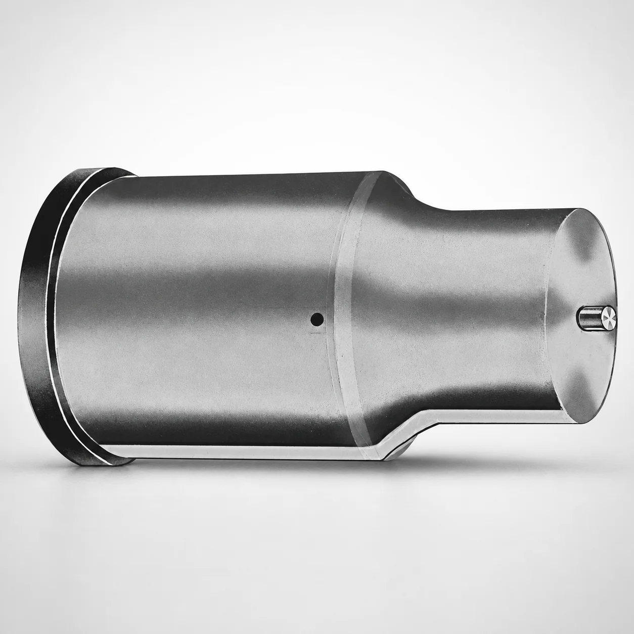
Extended Range Ejector Punches Metric XNP Coating
Extended Range Ejector Punches Metric XNP Coating (DAYTON) are designed to deliver reliable ejection performance in tooling where longer reach is required. Use the extended range punch geometry to support consistent part release and stable cycle operation.
- Extended range ejector punch design supports long-reach ejection in die tooling
- XNP coating helps improve wear resistance for repeated production cycles
- Metric shank and point geometry supports dependable fit for standardized toolsets
- DAYTON LAMINA part formatting simplifies ordering and maintenance workflow
Specifications
50 configurations available
| Tip shape | D (Shank dia.) (mm) | L1 (Point Length) (mm) | L (Length) (mm) | P Dimension (mm) | W Dimension (mm) | R Dimension (mm) |
|---|---|---|---|---|---|---|
| H | 40 | 25 ~ 30 | 63 ~ 100 | 20 ~ 39.95 | 8 ~ 39.95 | - |
| H | 45 | 25 ~ 30 | 63 ~ 100 | 25 ~ 44.95 | 9 ~ 44.95 | - |
| H | 50 | 25 ~ 30 | 63 ~ 100 | 30 ~ 49.95 | 10 ~ 49.95 | - |
| H | 56 | 25 ~ 30 | 63 ~ 100 | 35 ~ 55.95 | 11 ~ 55.95 | - |
| H | 63 | 25 ~ 30 | 63 ~ 100 | 40 ~ 62.95 | 12 ~ 62.95 | - |
| J | 40 | 25 ~ 30 | 63 ~ 100 | 20 ~ 39.95 | 8 ~ 39.95 | - |
| J | 45 | 25 ~ 30 | 63 ~ 100 | 25 ~ 44.95 | 9 ~ 44.95 | - |
| J | 50 | 25 ~ 30 | 63 ~ 100 | 30 ~ 49.95 | 10 ~ 49.95 | - |
| J | 56 | 25 ~ 30 | 63 ~ 100 | 35 ~ 55.95 | 11 ~ 55.95 | - |
| J | 63 | 25 ~ 30 | 63 ~ 100 | 40 ~ 62.95 | 12 ~ 62.95 | - |
| K | 40 | 25 ~ 30 | 63 ~ 100 | 20 ~ 39.95 | 8 ~ 39.95 | 0.2 ~ 19.975 |
| K | 45 | 25 ~ 30 | 63 ~ 100 | 25 ~ 44.95 | 9 ~ 44.95 | 0.2 ~ 22.475 |
| K | 50 | 25 ~ 30 | 63 ~ 100 | 30 ~ 49.95 | 10 ~ 49.95 | 0.2 ~ 24.975 |
| K | 56 | 25 ~ 30 | 63 ~ 100 | 35 ~ 55.95 | 11 ~ 55.95 | 0.2 ~ 27.975 |
| K | 63 | 25 ~ 30 | 63 ~ 100 | 40 ~ 62.95 | 12 ~ 62.95 | 0.2 ~ 31.475 |
| N | 40 | 25 ~ 30 | 63 ~ 100 | - | 8 ~ 39.95 | - |
| N | 45 | 25 ~ 30 | 63 ~ 100 | - | 9 ~ 44.95 | - |
| N | 50 | 25 ~ 30 | 63 ~ 100 | - | 10 ~ 49.95 | - |
| N | 56 | 25 ~ 30 | 63 ~ 100 | - | 11 ~ 55.95 | - |
| N | 63 | 25 ~ 30 | 63 ~ 100 | - | 12 ~ 62.95 | - |
| O | 40 | 25 ~ 30 | 63 ~ 100 | 20 ~ 39.95 | 8 ~ 39.95 | - |
| O | 45 | 25 ~ 30 | 63 ~ 100 | 25 ~ 44.95 | 9 ~ 44.95 | - |
| O | 50 | 25 ~ 30 | 63 ~ 100 | 30 ~ 49.95 | 10 ~ 49.95 | - |
| O | 56 | 25 ~ 30 | 63 ~ 100 | 35 ~ 55.95 | 11 ~ 55.95 | - |
| O | 63 | 25 ~ 30 | 63 ~ 100 | 40 ~ 62.95 | 12 ~ 62.95 | - |
| R | 40 | 25 ~ 30 | 63 ~ 100 | 20 ~ 39.95 | 8 ~ 39.95 | - |
| R | 45 | 25 ~ 30 | 63 ~ 100 | 25 ~ 44.95 | 9 ~ 44.95 | - |
| R | 50 | 25 ~ 30 | 63 ~ 100 | 30 ~ 49.95 | 10 ~ 49.95 | - |
| R | 56 | 25 ~ 30 | 63 ~ 100 | 35 ~ 55.95 | 11 ~ 55.95 | - |
| R | 63 | 25 ~ 30 | 63 ~ 100 | 40 ~ 62.95 | 12 ~ 62.95 | - |
| V | 40 | 25 ~ 30 | 63 ~ 100 | 20 ~ 39.95 | 8 ~ 39.95 | - |
| V | 45 | 25 ~ 30 | 63 ~ 100 | 25 ~ 44.95 | 9 ~ 44.95 | - |
| V | 50 | 25 ~ 30 | 63 ~ 100 | 30 ~ 49.95 | 10 ~ 49.95 | - |
| V | 56 | 25 ~ 30 | 63 ~ 100 | 35 ~ 55.95 | 11 ~ 55.95 | - |
| V | 63 | 25 ~ 30 | 63 ~ 100 | 40 ~ 62.95 | 12 ~ 62.95 | - |
| X | 40 | 25 ~ 30 | 63 ~ 100 | 20 ~ 39.95 | - | - |
| X | 45 | 25 ~ 30 | 63 ~ 100 | 25 ~ 44.95 | - | - |
| X | 50 | 25 ~ 30 | 63 ~ 100 | 30 ~ 49.95 | - | - |
| X | 56 | 25 ~ 30 | 63 ~ 100 | 35 ~ 55.95 | - | - |
| X | 63 | 25 ~ 30 | 63 ~ 100 | 40 ~ 62.95 | - | - |
| Y | 40 | 25 ~ 30 | 63 ~ 100 | 20 ~ 39.95 | 8 ~ 39.95 | 0.2 ~ 19.975 |
| Y | 45 | 25 ~ 30 | 63 ~ 100 | 25 ~ 44.95 | 9 ~ 44.95 | 0.2 ~ 22.475 |
| Y | 50 | 25 ~ 30 | 63 ~ 100 | 30 ~ 49.95 | 10 ~ 49.95 | 0.2 ~ 24.975 |
| Y | 56 | 25 ~ 30 | 63 ~ 100 | 35 ~ 55.95 | 11 ~ 55.95 | 0.2 ~ 27.975 |
| Y | 63 | 25 ~ 30 | 63 ~ 100 | 40 ~ 62.95 | 12 ~ 62.95 | 0.2 ~ 31.475 |
| Z | 40 | 25 ~ 30 | 63 ~ 100 | - | 8 ~ 39.95 | 0.2 ~ 19.975 |
| Z | 45 | 25 ~ 30 | 63 ~ 100 | - | 9 ~ 44.95 | 0.2 ~ 22.475 |
| Z | 50 | 25 ~ 30 | 63 ~ 100 | - | 10 ~ 49.95 | 0.2 ~ 24.975 |
| Z | 56 | 25 ~ 30 | 63 ~ 100 | - | 11 ~ 55.95 | 0.2 ~ 27.975 |
| Z | 63 | 25 ~ 30 | 63 ~ 100 | - | 12 ~ 62.95 | 0.2 ~ 31.475 |
Product Guide
Application Scenarios+
Extended-range ejection punches are used in injection mold and die tooling where the ejector requires additional reach to push parts out evenly. The extended geometry supports stable ejection during high-cycle production, helping reduce sticking and uneven release on deeper features.
- Automotive interior connector and trim tooling: When gate/runner layouts or deep ribs require longer travel, the extended point and metric shank help achieve consistent part release across the cavity.
- Consumer electronics housings: For thin-wall parts with bosses and undercuts, the extended reach supports uniform ejection forces without relying on exaggerated core deflection.
- General die applications: In tooling that sees frequent actuator cycles, the XNP coating is suited for wear-prone ejector tips and guide contact areas.
This variant’s metric construction and selectable point/tip shapes (H, J, K, N, O, R, V, X, Y, Z) make it compatible with standardized tool sets while the XNP coating improves wear resistance for repeated production runs.
Material & Process Details+
The provided configuration specifies an XNP coating for wear resistance, but no base steel grade or hardness value (HRC) is included in the available product data. As a result, material heat treatment details such as quench & tempering, nitriding, or retained-austenite control cannot be stated from the supplied specifications.
- Coating effect (XNP): Designed to improve surface durability of the ejector punch during repeated ejection cycles, reducing abrasion and tip wear in production.
- Wear vs. toughness trade-off: Coatings generally enhance wear life at the contact surfaces; however, overall toughness is still determined by the underlying punch steel and heat treatment.
- Material comparison: No alternative steel grades are listed for this series in the provided data, so direct comparisons cannot be made.
For a confirmed hardness (HRC) target and heat-treatment state, request the specific material certificate or drawing for series code 250301827751.
Sizing & Selection Guide+
Select the ejector punch based on the required total insertion length, point length, and the space available in your mold plate stack. This series offers L = 63 ~ 100 mm (fixed) and L1 (point length) = 25 ~ 30 mm (fixed), so choose the L that matches the core/cavity depth and safe clearance to the parting line and ejector return travel.
- Shank diameter (D): Choose from 40, 45, 50, 56, 63 mm to match the ejector hole/bushing or guide bore design.
- Contact and clearance dimensions (P, W, R): Use P/W ranges (20 ~ 39.95, 25 ~ 44.95, 30 ~ 49.95, 35 ~ 55.95, 40 ~ 62.95 for P; and corresponding W ranges) to align tip geometry with the part’s ejection contact area.
- Radius/edge blend (R): Select R from 0.2 ~ 19.975 up to 0.2 ~ 31.475 depending on required stress distribution and clearance around ribs/undercuts.
Because specific tolerance values are not provided, confirm fit strategy (clearance vs. interference) against your standard ejector bushing/hole tolerances and toolmaker practice for this series.
Frequently Asked Questions
Which tip shapes (H/J/K/N/O/R/V/X/Y/Z) are available for extended range ejector punches in this series?+
This series lists the following tip shape options: H, J, K, N, O, R, V, X, Y, Z. Choose the shape that best matches the part geometry and the required ejection contact profile at the point.
How do I choose the correct punch length L for a mold with deeper parting line depth?+
The L (overall length) is fixed across the series in the range 63 ~ 100 mm. Select the L that provides the needed reach to the ejection contact while maintaining clearance for ejector stroke and avoiding interference with nearby cores or shutoff components.
What are the allowable point length L1 values, and how do they affect part ejection contact?+
The L1 (point length) is fixed in the range 25 ~ 30 mm. A longer point length can improve contact coverage on deeper features, while the correct L1 helps avoid point over-travel into sensitive areas of the mold or part.
How does the XNP coating impact wear life for ejector punches in production?+
The series specifies XNP coating intended to improve wear resistance for repeated production cycles. In practice, it helps protect the ejector contact surfaces from abrasion during high-frequency ejection and release.
How do the shank diameter options (D) and geometry dimensions (P, W, R) map to mold guide/bushing design?+
The shank diameter D is available at 40, 45, 50, 56, 63 mm, which should match your ejector hole or guide/bushing bore sizing. Geometry parameters P, W, and R define the point profile and edge blend (with ranges provided in the specifications), so align them to the part’s ejection contact area and clearance requirements.
Related Products






Need Custom Specifications?
Our engineering team can help with custom configurations, material selection, and volume pricing.