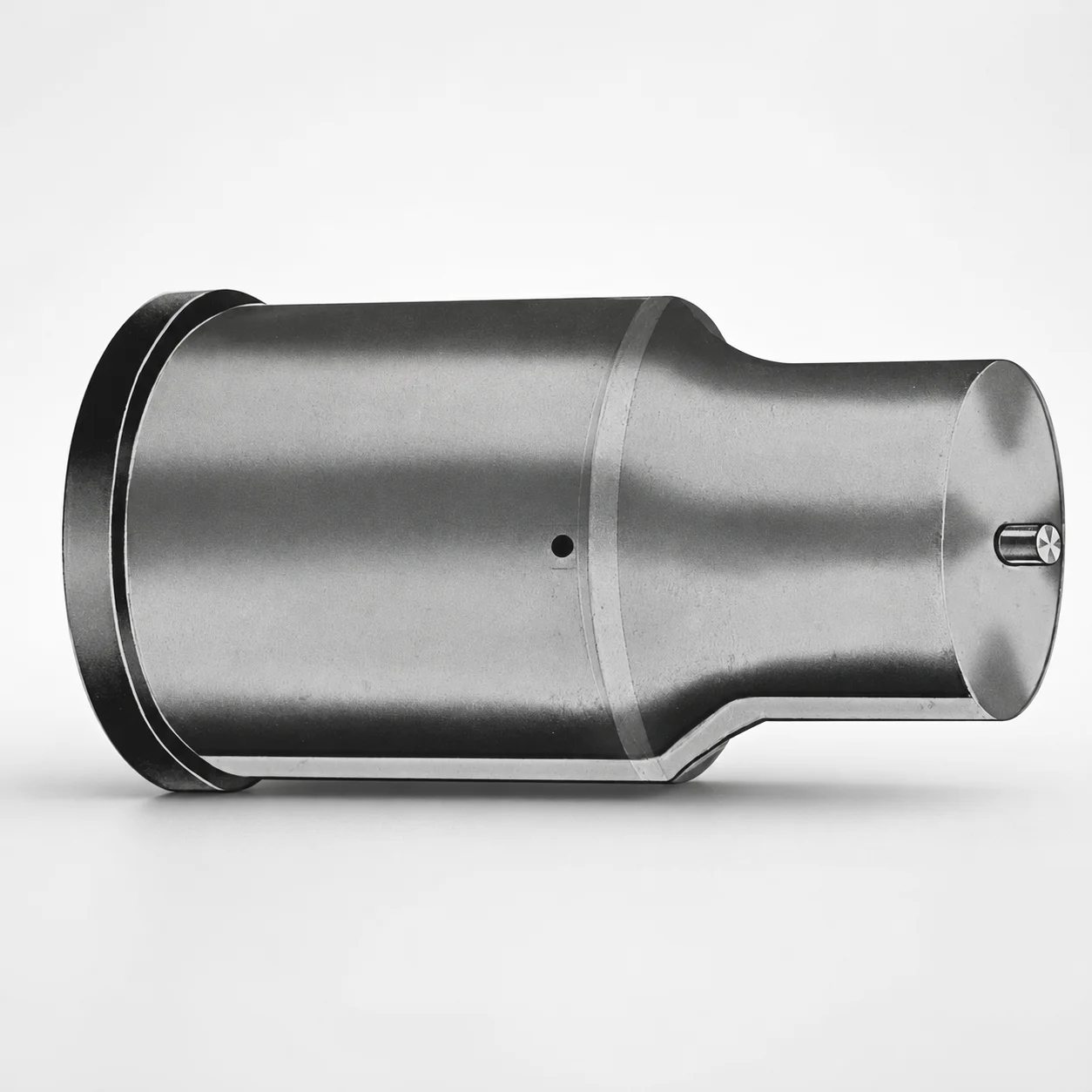
Extended Range Jector Punches Metric XNAP Coating
Extended Range Jector Punches (Metric) with XNAP coating are engineered for stable ejection and long service life in precision press tooling. The extended punch length helps maintain performance in deeper die cavities.
- Extended-range geometry supports consistent ejection in deeper tooling.
- XNAP coating enhances surface durability for abrasive, high-cycle work.
- Available tip shapes (X, R, K, O, H, J, N, V, Y, Z) for matching die contact needs.
- Standardized part numbering supports faster engineering selection.
Specifications
50 configurations available
| Tip shape | D (Shank dia.) (mm) | L1 (Point Length) (mm) | L (Length) (mm) | P Dimension (mm) | W Dimension (mm) | R Dimension (mm) |
|---|---|---|---|---|---|---|
| H | 40 | 25 ~ 30 | 63 ~ 100 | 20 ~ 39.95 | 8 ~ 39.95 | - |
| H | 45 | 25 ~ 30 | 63 ~ 100 | 25 ~ 44.95 | 9 ~ 44.95 | - |
| H | 50 | 25 ~ 30 | 63 ~ 100 | 30 ~ 49.95 | 10 ~ 49.95 | - |
| H | 56 | 25 ~ 30 | 63 ~ 100 | 35 ~ 55.95 | 11 ~ 55.95 | - |
| H | 63 | 25 ~ 30 | 63 ~ 100 | 40 ~ 62.95 | 12 ~ 62.95 | - |
| J | 40 | 25 ~ 30 | 63 ~ 100 | 20 ~ 39.95 | 8 ~ 39.95 | - |
| J | 45 | 25 ~ 30 | 63 ~ 100 | 25 ~ 44.95 | 9 ~ 44.95 | - |
| J | 50 | 25 ~ 30 | 63 ~ 100 | 30 ~ 49.95 | 10 ~ 49.95 | - |
| J | 56 | 25 ~ 30 | 63 ~ 100 | 35 ~ 55.95 | 11 ~ 55.95 | - |
| J | 63 | 25 ~ 30 | 63 ~ 100 | 40 ~ 62.95 | 12 ~ 62.95 | - |
| K | 40 | 25 ~ 30 | 63 ~ 100 | 20 ~ 39.95 | 8 ~ 39.95 | 0.2 ~ 19.975 |
| K | 45 | 25 ~ 30 | 63 ~ 100 | 25 ~ 44.95 | 9 ~ 44.95 | 0.2 ~ 22.475 |
| K | 50 | 25 ~ 30 | 63 ~ 100 | 30 ~ 49.95 | 10 ~ 49.95 | 0.2 ~ 24.975 |
| K | 56 | 25 ~ 30 | 63 ~ 100 | 35 ~ 55.95 | 11 ~ 55.95 | 0.2 ~ 27.975 |
| K | 63 | 25 ~ 30 | 63 ~ 100 | 40 ~ 62.95 | 12 ~ 62.95 | 0.2 ~ 31.475 |
| N | 40 | 25 ~ 30 | 63 ~ 100 | - | 8 ~ 39.95 | - |
| N | 45 | 25 ~ 30 | 63 ~ 100 | - | 9 ~ 44.95 | - |
| N | 50 | 25 ~ 30 | 63 ~ 100 | - | 10 ~ 49.95 | - |
| N | 56 | 25 ~ 30 | 63 ~ 100 | - | 11 ~ 55.95 | - |
| N | 63 | 25 ~ 30 | 63 ~ 100 | - | 12 ~ 62.95 | - |
| O | 40 | 25 ~ 30 | 63 ~ 100 | 20 ~ 39.95 | 8 ~ 39.95 | - |
| O | 45 | 25 ~ 30 | 63 ~ 100 | 25 ~ 44.95 | 9 ~ 44.95 | - |
| O | 50 | 25 ~ 30 | 63 ~ 100 | 30 ~ 49.95 | 10 ~ 49.95 | - |
| O | 56 | 25 ~ 30 | 63 ~ 100 | 35 ~ 55.95 | 11 ~ 55.95 | - |
| O | 63 | 25 ~ 30 | 63 ~ 100 | 40 ~ 62.95 | 12 ~ 62.95 | - |
| R | 40 | 25 ~ 30 | 63 ~ 100 | 20 ~ 39.95 | 8 ~ 39.95 | - |
| R | 45 | 25 ~ 30 | 63 ~ 100 | 25 ~ 44.95 | 9 ~ 44.95 | - |
| R | 50 | 25 ~ 30 | 63 ~ 100 | 30 ~ 49.95 | 10 ~ 49.95 | - |
| R | 56 | 25 ~ 30 | 63 ~ 100 | 35 ~ 55.95 | 11 ~ 55.95 | - |
| R | 63 | 25 ~ 30 | 63 ~ 100 | 40 ~ 62.95 | 12 ~ 62.95 | - |
| V | 40 | 25 ~ 30 | 63 ~ 100 | 20 ~ 39.95 | 8 ~ 39.95 | - |
| V | 45 | 25 ~ 30 | 63 ~ 100 | 25 ~ 44.95 | 9 ~ 44.95 | - |
| V | 50 | 25 ~ 30 | 63 ~ 100 | 30 ~ 49.95 | 10 ~ 49.95 | - |
| V | 56 | 25 ~ 30 | 63 ~ 100 | 35 ~ 55.95 | 11 ~ 55.95 | - |
| V | 63 | 25 ~ 30 | 63 ~ 100 | 40 ~ 62.95 | 12 ~ 62.95 | - |
| X | 40 | 25 ~ 30 | 63 ~ 100 | 20 ~ 39.95 | - | - |
| X | 45 | 25 ~ 30 | 63 ~ 100 | 25 ~ 44.95 | - | - |
| X | 50 | 25 ~ 30 | 63 ~ 100 | 30 ~ 49.95 | - | - |
| X | 56 | 25 ~ 30 | 63 ~ 100 | 35 ~ 55.95 | - | - |
| X | 63 | 25 ~ 30 | 63 ~ 100 | 40 ~ 62.95 | - | - |
| Y | 40 | 25 ~ 30 | 63 ~ 100 | 20 ~ 39.95 | 8 ~ 39.95 | 0.2 ~ 19.975 |
| Y | 45 | 25 ~ 30 | 63 ~ 100 | 25 ~ 44.95 | 9 ~ 44.95 | 0.2 ~ 22.475 |
| Y | 50 | 25 ~ 30 | 63 ~ 100 | 30 ~ 49.95 | 10 ~ 49.95 | 0.2 ~ 24.975 |
| Y | 56 | 25 ~ 30 | 63 ~ 100 | 35 ~ 55.95 | 11 ~ 55.95 | 0.2 ~ 27.975 |
| Y | 63 | 25 ~ 30 | 63 ~ 100 | 40 ~ 62.95 | 12 ~ 62.95 | 0.2 ~ 31.475 |
| Z | 40 | 25 ~ 30 | 63 ~ 100 | - | 8 ~ 39.95 | 0.2 ~ 19.975 |
| Z | 45 | 25 ~ 30 | 63 ~ 100 | - | 9 ~ 44.95 | 0.2 ~ 22.475 |
| Z | 50 | 25 ~ 30 | 63 ~ 100 | - | 10 ~ 49.95 | 0.2 ~ 24.975 |
| Z | 56 | 25 ~ 30 | 63 ~ 100 | - | 11 ~ 55.95 | 0.2 ~ 27.975 |
| Z | 63 | 25 ~ 30 | 63 ~ 100 | - | 12 ~ 62.95 | 0.2 ~ 31.475 |
Product Guide
Application Scenarios+
This extended-range jector punch is used in precision press and die tooling where reliable ejection is needed after deep or tightly packed forming operations. The longer punch length (L = 63–100 mm) helps keep full contact and stable ejection performance in deeper die cavities, reducing the risk of incomplete part release.
- Automotive and industrial connector press tooling: Use the metric geometry to support consistent ejection through deeper forming sections. The XNAP coating improves surface durability under high-cycle, abrasive contact.
- Electronics and stamped component dies: Select the appropriate tip shape (H, J, K, N, O, R, V, X, Y, Z) to match die contact requirements and maintain dimensional stability at the punch point.
- General high-cycle production dies: The fixed point length L1 = 25–30 mm supports predictable contact length for repeatable release behavior.
Material & Process Details+
The provided product specifications focus on geometry and coating, but do not state the underlying steel grade. Therefore, material-grade equivalence (e.g., SKD61/H13 or M2 equivalents) and explicit heat-treatment data cannot be asserted from the given dataset.
What can be confirmed is the surface protection: XNAP coating is specified for improved wear resistance. In die and punch service, this typically supports higher sliding/abrasive durability during repeated ejection cycles.
- Wear resistance vs. toughness: Coatings generally improve surface hardness and reduce abrasive wear while the punch core toughness remains governed by the base steel and its heat treatment (not provided here).
- Heat treatment state: Not listed in the supplied specifications; confirm the core hardness and temper condition with the manufacturer data sheet before final process sign-off.
Sizing & Selection Guide+
Select dimensions by matching the punch’s working geometry to the die cavity/core contact requirements while maintaining alignment during press ejection.
- Overall length (L): Choose L = 63–100 mm to reach through deeper die sections while still maintaining stable engagement. For controlled contact length, use L1 (point length) = 25–30 mm as the effective point region.
- Shank diameter (D): Pick D = 40, 45, 50, 56, or 63 mm based on the punch guide/bushing and clearance in the tooling stack-up.
- Contact geometry via P/W/R: Use the available ranges of P = 20–39.95, 25–44.95, 30–49.95, 35–55.95, 40–62.95 mm, W = 8–39.95, 9–44.95, 10–49.95, 11–55.95, 12–62.95 mm, and R = 0.2–19.975 up to 0.2–31.475 mm to match die pocket radius/relief needs for your chosen tip shape.
Confirm fit using your existing guide tolerance and press tolerancing strategy. The dataset provides dimension ranges but does not include explicit tolerance values, so final allowance checks should follow your internal drawings and supplier tolerance sheets.
Frequently Asked Questions
How do I choose the correct extended punch length (L = 63–100 mm) for deep die ejection?+
Which tip shape options (H, J, K, N, O, R, V, X, Y, Z) should be used to match die contact geometry?+
How do the shank diameter options (D = 40/45/50/56/63 mm) affect punch guidance and tooling compatibility?+
What do the variable geometry parameters P, W, and R mean for die matching?+
What benefit does the XNAP coating provide, and is base material heat treatment specified?+
Related Products






Need Custom Specifications?
Our engineering team can help with custom configurations, material selection, and volume pricing.