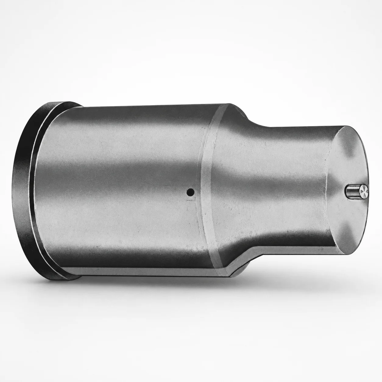
Extended Range Jector Punches - Metric, XN DayTride® Coating
Extended Range Jector Punches - Metric, XN DayTride® Coating provide consistent punch extension for long-stroke ejector applications. The XN DayTride® coated surface supports stable performance under repetitive press cycles.
- Extended range ejector geometry for improved reach in tooling
- XN DayTride® coating helps reduce wear during punch service
- Metric punch construction with selectable tip shapes for fitment
- Suitable for die sets where long point length is required
Specifications
50 configurations available
| Tip shape | D (Shank dia.) (mm) | L1 (Point Length) (mm) | L (Length) (mm) | P Dimension (mm) | W Dimension (mm) | R Dimension (mm) |
|---|---|---|---|---|---|---|
| H | 40 | 25 ~ 30 | 63 ~ 100 | 20 ~ 39.95 | 8 ~ 39.95 | - |
| H | 45 | 25 ~ 30 | 63 ~ 100 | 25 ~ 44.95 | 9 ~ 44.95 | - |
| H | 50 | 25 ~ 30 | 63 ~ 100 | 30 ~ 49.95 | 10 ~ 49.95 | - |
| H | 56 | 25 ~ 30 | 63 ~ 100 | 35 ~ 55.95 | 11 ~ 55.95 | - |
| H | 63 | 25 ~ 30 | 63 ~ 100 | 40 ~ 62.95 | 12 ~ 62.95 | - |
| J | 40 | 25 ~ 30 | 63 ~ 100 | 20 ~ 39.95 | 8 ~ 39.95 | - |
| J | 45 | 25 ~ 30 | 63 ~ 100 | 25 ~ 44.95 | 9 ~ 44.95 | - |
| J | 50 | 25 ~ 30 | 63 ~ 100 | 30 ~ 49.95 | 10 ~ 49.95 | - |
| J | 56 | 25 ~ 30 | 63 ~ 100 | 35 ~ 55.95 | 11 ~ 55.95 | - |
| J | 63 | 25 ~ 30 | 63 ~ 100 | 40 ~ 62.95 | 12 ~ 62.95 | - |
| K | 40 | 25 ~ 30 | 63 ~ 100 | 20 ~ 39.95 | 8 ~ 39.95 | 0.2 ~ 19.975 |
| K | 45 | 25 ~ 30 | 63 ~ 100 | 25 ~ 44.95 | 9 ~ 44.95 | 0.2 ~ 22.475 |
| K | 50 | 25 ~ 30 | 63 ~ 100 | 30 ~ 49.95 | 10 ~ 49.95 | 0.2 ~ 24.975 |
| K | 56 | 25 ~ 30 | 63 ~ 100 | 35 ~ 55.95 | 11 ~ 55.95 | 0.2 ~ 27.975 |
| K | 63 | 25 ~ 30 | 63 ~ 100 | 40 ~ 62.95 | 12 ~ 62.95 | 0.2 ~ 31.475 |
| N | 40 | 25 ~ 30 | 63 ~ 100 | - | 8 ~ 39.95 | - |
| N | 45 | 25 ~ 30 | 63 ~ 100 | - | 9 ~ 44.95 | - |
| N | 50 | 25 ~ 30 | 63 ~ 100 | - | 10 ~ 49.95 | - |
| N | 56 | 25 ~ 30 | 63 ~ 100 | - | 11 ~ 55.95 | - |
| N | 63 | 25 ~ 30 | 63 ~ 100 | - | 12 ~ 62.95 | - |
| O | 40 | 25 ~ 30 | 63 ~ 100 | 20 ~ 39.95 | 8 ~ 39.95 | - |
| O | 45 | 25 ~ 30 | 63 ~ 100 | 25 ~ 44.95 | 9 ~ 44.95 | - |
| O | 50 | 25 ~ 30 | 63 ~ 100 | 30 ~ 49.95 | 10 ~ 49.95 | - |
| O | 56 | 25 ~ 30 | 63 ~ 100 | 35 ~ 55.95 | 11 ~ 55.95 | - |
| O | 63 | 25 ~ 30 | 63 ~ 100 | 40 ~ 62.95 | 12 ~ 62.95 | - |
| R | 40 | 25 ~ 30 | 63 ~ 100 | 20 ~ 39.95 | 8 ~ 39.95 | - |
| R | 45 | 25 ~ 30 | 63 ~ 100 | 25 ~ 44.95 | 9 ~ 44.95 | - |
| R | 50 | 25 ~ 30 | 63 ~ 100 | 30 ~ 49.95 | 10 ~ 49.95 | - |
| R | 56 | 25 ~ 30 | 63 ~ 100 | 35 ~ 55.95 | 11 ~ 55.95 | - |
| R | 63 | 25 ~ 30 | 63 ~ 100 | 40 ~ 62.95 | 12 ~ 62.95 | - |
| V | 40 | 25 ~ 30 | 63 ~ 100 | 20 ~ 39.95 | 8 ~ 39.95 | - |
| V | 45 | 25 ~ 30 | 63 ~ 100 | 25 ~ 44.95 | 9 ~ 44.95 | - |
| V | 50 | 25 ~ 30 | 63 ~ 100 | 30 ~ 49.95 | 10 ~ 49.95 | - |
| V | 56 | 25 ~ 30 | 63 ~ 100 | 35 ~ 55.95 | 11 ~ 55.95 | - |
| V | 63 | 25 ~ 30 | 63 ~ 100 | 40 ~ 62.95 | 12 ~ 62.95 | - |
| X | 40 | 25 ~ 30 | 63 ~ 100 | 20 ~ 39.95 | - | - |
| X | 45 | 25 ~ 30 | 63 ~ 100 | 25 ~ 44.95 | - | - |
| X | 50 | 25 ~ 30 | 63 ~ 100 | 30 ~ 49.95 | - | - |
| X | 56 | 25 ~ 30 | 63 ~ 100 | 35 ~ 55.95 | - | - |
| X | 63 | 25 ~ 30 | 63 ~ 100 | 40 ~ 62.95 | - | - |
| Y | 40 | 25 ~ 30 | 63 ~ 100 | 20 ~ 39.95 | 8 ~ 39.95 | 0.2 ~ 19.975 |
| Y | 45 | 25 ~ 30 | 63 ~ 100 | 25 ~ 44.95 | 9 ~ 44.95 | 0.2 ~ 22.475 |
| Y | 50 | 25 ~ 30 | 63 ~ 100 | 30 ~ 49.95 | 10 ~ 49.95 | 0.2 ~ 24.975 |
| Y | 56 | 25 ~ 30 | 63 ~ 100 | 35 ~ 55.95 | 11 ~ 55.95 | 0.2 ~ 27.975 |
| Y | 63 | 25 ~ 30 | 63 ~ 100 | 40 ~ 62.95 | 12 ~ 62.95 | 0.2 ~ 31.475 |
| Z | 40 | 25 ~ 30 | 63 ~ 100 | - | 8 ~ 39.95 | 0.2 ~ 19.975 |
| Z | 45 | 25 ~ 30 | 63 ~ 100 | - | 9 ~ 44.95 | 0.2 ~ 22.475 |
| Z | 50 | 25 ~ 30 | 63 ~ 100 | - | 10 ~ 49.95 | 0.2 ~ 24.975 |
| Z | 56 | 25 ~ 30 | 63 ~ 100 | - | 11 ~ 55.95 | 0.2 ~ 27.975 |
| Z | 63 | 25 ~ 30 | 63 ~ 100 | - | 12 ~ 62.95 | 0.2 ~ 31.475 |
Product Guide
Application Scenarios+
This extended-range jector punch is used in injection mold tooling where the ejector requires a longer reach to move parts reliably—especially when there is deeper shut-off height, longer undercuts, or taller inserts. The point length of L1 = 25–30 mm combined with overall length L = 63–100 mm helps maintain stable engagement without excessive flex.
- Automotive connector and sensor housings: common for parts with deep cavities and multiple inserts; the extended geometry supports consistent part ejection over repetitive press cycles.
- Consumer electronics enclosures: when ejector pins must reach recessed features, selectable tip shapes (H, J, K, N, O, R, V, X, Y, Z) improve fit with the mating die/insert.
- Medical device housings with tight dimensional control: the XN DayTride® coating is specified to reduce service wear, supporting longer tool life in high-cycle environments.
Material & Process Details+
The provided specifications identify the coating and geometry, but do not list a specific steel grade. For this reason, material-property claims are limited to what can be supported: the punch uses an XN DayTride® coating designed to improve wear performance under repetitive ejector loading.
- Wear resistance: the XN DayTride® coating helps reduce abrasive and adhesive wear at the punch service surface, supporting longer life during frequent press cycles.
- Toughness trade-off: surface coatings typically prioritize wear resistance; they work best when underlying steel toughness and proper support align with the required length (L = 63–100 mm) to limit bending stresses.
- Heat treatment state: not specified in the input data (e.g., nitrided or quenched & tempered state is not provided).
If you need confirmed hardness (HRC) or the steel grade/heat-treatment recipe, share the intended cavity/core material and operating cycle count so we can align the recommended grade and treatment.
Sizing & Selection Guide+
Select the jector punch by matching the point length, overall length, and shank diameter to the ejector system and the receiving die geometry. Start with L1 (point length) = 25–30 mm to ensure the punch penetrates the required depth for reliable part release without bottoming.
- Overall length: choose L = 63–100 mm so the working point reaches the cavity feature while maintaining sufficient support length in the ejector guide/support.
- Shank diameter: match D (shank dia.) = 40, 45, 50, 56, 63 mm to the leader/ejector bore and any standard mounting clearances.
- Tip shape compatibility: select one tip shape (H, J, K, N, O, R, V, X, Y, Z) that fits the mating die pocket/insert geometry.
Dimensions P, W, and R are available in multiple ranges (e.g., P = 20–39.95 mm up to 40–62.95 mm; W = 8–39.95 mm up to 12–62.95 mm; R = 0.2–19.975 mm up to 0.2–31.475 mm). Use these to align with the cutter/guide radii and seating features; where functional clearance is required, keep tolerances consistent with your die-set and ejector guide tolerancing strategy.
Frequently Asked Questions
How do I choose the correct point length (L1) for reliable ejection in a deep cavity die set?+
Use L1 = 25–30 mm to cover the required working depth to reach the part feature that must be released. Then verify the overall length L = 63–100 mm provides enough reach without causing bottoming or excessive bending in long-stroke ejector layouts.
Which tip shape (H, J, K, N, O, R, V, X, Y, Z) should I select to match the mating die pocket geometry?+
Tip shapes are intended for fitment with the receiving die/insert geometry; select the one that mates correctly with your pocket contour and support area. If you are matching a specific seating radius or corner profile, also align the available R range (e.g., 0.2–19.975 to 0.2–31.475 mm depending on configuration).
What shank diameter (D) options are available, and how do they affect ejector bore/guide fit?+
The available shank diameters are D = 40, 45, 50, 56, 63 mm. Match D to the leader/ejector bore and your standard clearance strategy; if your guide system uses tighter fits, confirm your drawing tolerances before locking the ejector stack-up.
Can the XN DayTride® coating be selected as a wear-control feature for high-cycle ejector service?+
This series specifies an XN DayTride® coating intended to reduce wear during punch service under repetitive press cycles. It is particularly relevant when ejector surfaces experience frequent sliding/impact and you need improved wear performance without changing the ejector geometry.
How should I use the P, W, and R dimensions when designing the ejector retention or seating features?+
Choose from the provided configuration ranges to match your retention or seating geometry: P (e.g., 20–39.95 up to 40–62.95 mm), W (e.g., 8–39.95 up to 12–62.95 mm), and R (e.g., 0.2–19.975 up to 0.2–31.475 mm). Use these dimensions to ensure proper seating contact and radius match while maintaining functional clearance for assembly.
Related Products






Need Custom Specifications?
Our engineering team can help with custom configurations, material selection, and volume pricing.