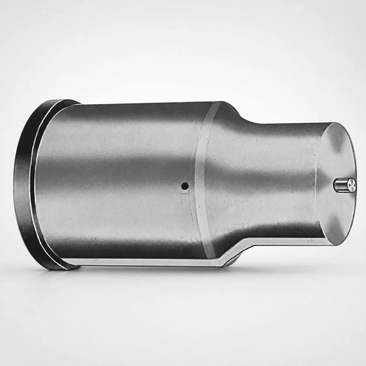
Extended Range Ejector Punches Metric XAN DayTAN™ Coating
Extended Range ejector punches are metric punches engineered for stable ejection over long stroke ranges. The XAN DayTAN™ coating supports controlled wear and consistent performance in production tooling.
- Extended range geometry maintains contact and straight ejection
- XAN DayTAN™ coated surface helps reduce galling and wear
- Compatible with metric punchholder systems for efficient setup
- Used in blanking and forming dies requiring dependable punch return
Specifications
50 configurations available
| Tip shape | D (Shank dia.) (mm) | L1 (Point Length) (mm) | L (Length) (mm) | P Dimension (mm) | W Dimension (mm) | R Dimension (mm) |
|---|---|---|---|---|---|---|
| H | 40 | 25 ~ 30 | 63 ~ 100 | 20 ~ 39.95 | 8 ~ 39.95 | - |
| H | 45 | 25 ~ 30 | 63 ~ 100 | 25 ~ 44.95 | 9 ~ 44.95 | - |
| H | 50 | 25 ~ 30 | 63 ~ 100 | 30 ~ 49.95 | 10 ~ 49.95 | - |
| H | 56 | 25 ~ 30 | 63 ~ 100 | 35 ~ 55.95 | 11 ~ 55.95 | - |
| H | 63 | 25 ~ 30 | 63 ~ 100 | 40 ~ 62.95 | 12 ~ 62.95 | - |
| J | 40 | 25 ~ 30 | 63 ~ 100 | 20 ~ 39.95 | 8 ~ 39.95 | - |
| J | 45 | 25 ~ 30 | 63 ~ 100 | 25 ~ 44.95 | 9 ~ 44.95 | - |
| J | 50 | 25 ~ 30 | 63 ~ 100 | 30 ~ 49.95 | 10 ~ 49.95 | - |
| J | 56 | 25 ~ 30 | 63 ~ 100 | 35 ~ 55.95 | 11 ~ 55.95 | - |
| J | 63 | 25 ~ 30 | 63 ~ 100 | 40 ~ 62.95 | 12 ~ 62.95 | - |
| K | 40 | 25 ~ 30 | 63 ~ 100 | 20 ~ 39.95 | 8 ~ 39.95 | 0.2 ~ 19.975 |
| K | 45 | 25 ~ 30 | 63 ~ 100 | 25 ~ 44.95 | 9 ~ 44.95 | 0.2 ~ 22.475 |
| K | 50 | 25 ~ 30 | 63 ~ 100 | 30 ~ 49.95 | 10 ~ 49.95 | 0.2 ~ 24.975 |
| K | 56 | 25 ~ 30 | 63 ~ 100 | 35 ~ 55.95 | 11 ~ 55.95 | 0.2 ~ 27.975 |
| K | 63 | 25 ~ 30 | 63 ~ 100 | 40 ~ 62.95 | 12 ~ 62.95 | 0.2 ~ 31.475 |
| N | 40 | 25 ~ 30 | 63 ~ 100 | - | 8 ~ 39.95 | - |
| N | 45 | 25 ~ 30 | 63 ~ 100 | - | 9 ~ 44.95 | - |
| N | 50 | 25 ~ 30 | 63 ~ 100 | - | 10 ~ 49.95 | - |
| N | 56 | 25 ~ 30 | 63 ~ 100 | - | 11 ~ 55.95 | - |
| N | 63 | 25 ~ 30 | 63 ~ 100 | - | 12 ~ 62.95 | - |
| O | 40 | 25 ~ 30 | 63 ~ 100 | 20 ~ 39.95 | 8 ~ 39.95 | - |
| O | 45 | 25 ~ 30 | 63 ~ 100 | 25 ~ 44.95 | 9 ~ 44.95 | - |
| O | 50 | 25 ~ 30 | 63 ~ 100 | 30 ~ 49.95 | 10 ~ 49.95 | - |
| O | 56 | 25 ~ 30 | 63 ~ 100 | 35 ~ 55.95 | 11 ~ 55.95 | - |
| O | 63 | 25 ~ 30 | 63 ~ 100 | 40 ~ 62.95 | 12 ~ 62.95 | - |
| R | 40 | 25 ~ 30 | 63 ~ 100 | 20 ~ 39.95 | 8 ~ 39.95 | - |
| R | 45 | 25 ~ 30 | 63 ~ 100 | 25 ~ 44.95 | 9 ~ 44.95 | - |
| R | 50 | 25 ~ 30 | 63 ~ 100 | 30 ~ 49.95 | 10 ~ 49.95 | - |
| R | 56 | 25 ~ 30 | 63 ~ 100 | 35 ~ 55.95 | 11 ~ 55.95 | - |
| R | 63 | 25 ~ 30 | 63 ~ 100 | 40 ~ 62.95 | 12 ~ 62.95 | - |
| V | 40 | 25 ~ 30 | 63 ~ 100 | 20 ~ 39.95 | 8 ~ 39.95 | - |
| V | 45 | 25 ~ 30 | 63 ~ 100 | 25 ~ 44.95 | 9 ~ 44.95 | - |
| V | 50 | 25 ~ 30 | 63 ~ 100 | 30 ~ 49.95 | 10 ~ 49.95 | - |
| V | 56 | 25 ~ 30 | 63 ~ 100 | 35 ~ 55.95 | 11 ~ 55.95 | - |
| V | 63 | 25 ~ 30 | 63 ~ 100 | 40 ~ 62.95 | 12 ~ 62.95 | - |
| X | 40 | 25 ~ 30 | 63 ~ 100 | 20 ~ 39.95 | - | - |
| X | 45 | 25 ~ 30 | 63 ~ 100 | 25 ~ 44.95 | - | - |
| X | 50 | 25 ~ 30 | 63 ~ 100 | 30 ~ 49.95 | - | - |
| X | 56 | 25 ~ 30 | 63 ~ 100 | 35 ~ 55.95 | - | - |
| X | 63 | 25 ~ 30 | 63 ~ 100 | 40 ~ 62.95 | - | - |
| Y | 40 | 25 ~ 30 | 63 ~ 100 | 20 ~ 39.95 | 8 ~ 39.95 | 0.2 ~ 19.975 |
| Y | 45 | 25 ~ 30 | 63 ~ 100 | 25 ~ 44.95 | 9 ~ 44.95 | 0.2 ~ 22.475 |
| Y | 50 | 25 ~ 30 | 63 ~ 100 | 30 ~ 49.95 | 10 ~ 49.95 | 0.2 ~ 24.975 |
| Y | 56 | 25 ~ 30 | 63 ~ 100 | 35 ~ 55.95 | 11 ~ 55.95 | 0.2 ~ 27.975 |
| Y | 63 | 25 ~ 30 | 63 ~ 100 | 40 ~ 62.95 | 12 ~ 62.95 | 0.2 ~ 31.475 |
| Z | 40 | 25 ~ 30 | 63 ~ 100 | - | 8 ~ 39.95 | 0.2 ~ 19.975 |
| Z | 45 | 25 ~ 30 | 63 ~ 100 | - | 9 ~ 44.95 | 0.2 ~ 22.475 |
| Z | 50 | 25 ~ 30 | 63 ~ 100 | - | 10 ~ 49.95 | 0.2 ~ 24.975 |
| Z | 56 | 25 ~ 30 | 63 ~ 100 | - | 11 ~ 55.95 | 0.2 ~ 27.975 |
| Z | 63 | 25 ~ 30 | 63 ~ 100 | - | 12 ~ 62.95 | 0.2 ~ 31.475 |
Product Guide
Application Scenarios+
These extended-range ejector punches are used in injection and stamping-style mold tooling where ejector travel must remain stable over a long stroke. Their extended-range geometry helps maintain contact and promote straight ejection, reducing the risk of stick-slip during cycling.
- Automotive connector and housing tooling: Suitable for ejecting thick features or multi-part components where the ejector system needs consistent return and controlled wear under repeated production loads.
- Appliance and industrial enclosure dies: Works well for blanking and forming dies that require dependable punch return across longer strokes, especially when close-clearance operation can increase friction and galling.
- High-cycle production of formed sheets: The XAN DayTAN™ coated contact surface is designed to support controlled wear and help reduce galling, improving consistency over time.
This variant is engineered to perform in close-clearance tooling environments by combining a long-stroke punch profile with a wear-focused coating.
Material & Process Details+
The provided datasheet specifies the XAN DayTAN™ coated surface intended for controlled wear and reduced galling. However, no steel grade, heat-treatment state (e.g., quenched & tempered, nitrided), or target hardness (HRC) is included in the input parameters, so these values cannot be stated reliably.
- Coating role: The XAN DayTAN™ layer is used to improve tribological behavior at the punch-to-holder and guided-contact interfaces, supporting consistent performance in production cycles.
- Wear vs. toughness trade-off: In general, hardened substrate plus a wear-resistant coating improves resistance to abrasion, while toughness is primarily governed by the underlying steel and its heat treatment; specific substrate hardness and toughness cannot be confirmed from the current data.
If you share the steel grade or certification sheet for series 250301827852, we can document the exact equivalent grade, HRC range, and heat-treatment condition for engineering sign-off.
Sizing & Selection Guide+
To select the correct extended-range ejector punch, match the punch’s shank diameter (D) and overall length (L) to your punchholder and cavity/core clearance requirements. This series supports D = 40, 45, 50, 56, 63 mm and L = 63 to 100 mm.
- Point penetration / contact control: Use the fixed L1 = 25 to 30 mm to ensure the working point reaches the intended ejecting contact depth without bottoming in the guide system.
- Geometry matching: Select the tip shape among H, J, K, N, O, R, V, X, Y, Z based on part geometry and the required contact area.
- Guiding and clearance: Choose the correct P and W dimensions within the available ranges (e.g., P: 20–39.95 up to 40–62.95 mm depending on the configuration; W: 8–39.95 up to 12–62.95 mm) to fit the ejector track and interface envelope.
- Draft/relief (R): Confirm the R range (0.2 to 19.975 up to 0.2 to 31.475 mm) to maintain clearance at the transition zones.
Tolerance values are not provided in the input; verify fit to your punchholder bore and alignment features using your standard mold tolerances for this punch diameter.
Frequently Asked Questions
Which shank diameter options are available for series 250301827852, and how do they map to punchholder bore selection?+
This series offers D (Shank dia.) = 40, 45, 50, 56, 63 mm. Use the selected D to match the corresponding punchholder bore and guided interface so the ejector can move straight through the long-stroke travel.
How do I choose the correct overall length (L) and point length (L1) to avoid bottoming in the die during ejection?+
The overall L is available in a range of 63 to 100 mm, while the working point length is fixed at L1 = 25 to 30 mm. Select L to suit your stack height and actuator travel, then confirm L1 provides the required contact depth without interference inside the guided system.
What is the purpose of the XAN DayTAN™ coating on extended-range ejector punches in close-clearance tooling?+
The XAN DayTAN™ coated contact surface is intended to support controlled wear and help reduce galling. This is particularly relevant in close-clearance environments where higher friction and repeated cycles can otherwise degrade punch performance.
How do I select tip shape (H, J, K, N, O, R, V, X, Y, Z) for different part ejection geometries?+
The tip shape is specified as H, J, K, N, O, R, V, X, Y, Z for this extended-range series. Choose the tip profile based on the contact area you need on the molded/forming part and the clearance available at the ejector-to-part interface to maintain stable ejection.
For this series, how do P, W, and R dimensions relate to alignment and clearance in the ejector system?+
Configuration-specific ranges are provided for P and W (e.g., P: 20–39.95, 25–44.95, 30–49.95, 35–55.95, 40–62.95; W: 8–39.95, 9–44.95, 10–49.95, 11–55.95, 12–62.95) and for the radius R (0.2–19.975 up to 0.2–31.475). Select values that fit your punchholder interface and maintain the required clearances at transitions using your drawing tolerances.
Related Products






Need Custom Specifications?
Our engineering team can help with custom configurations, material selection, and volume pricing.