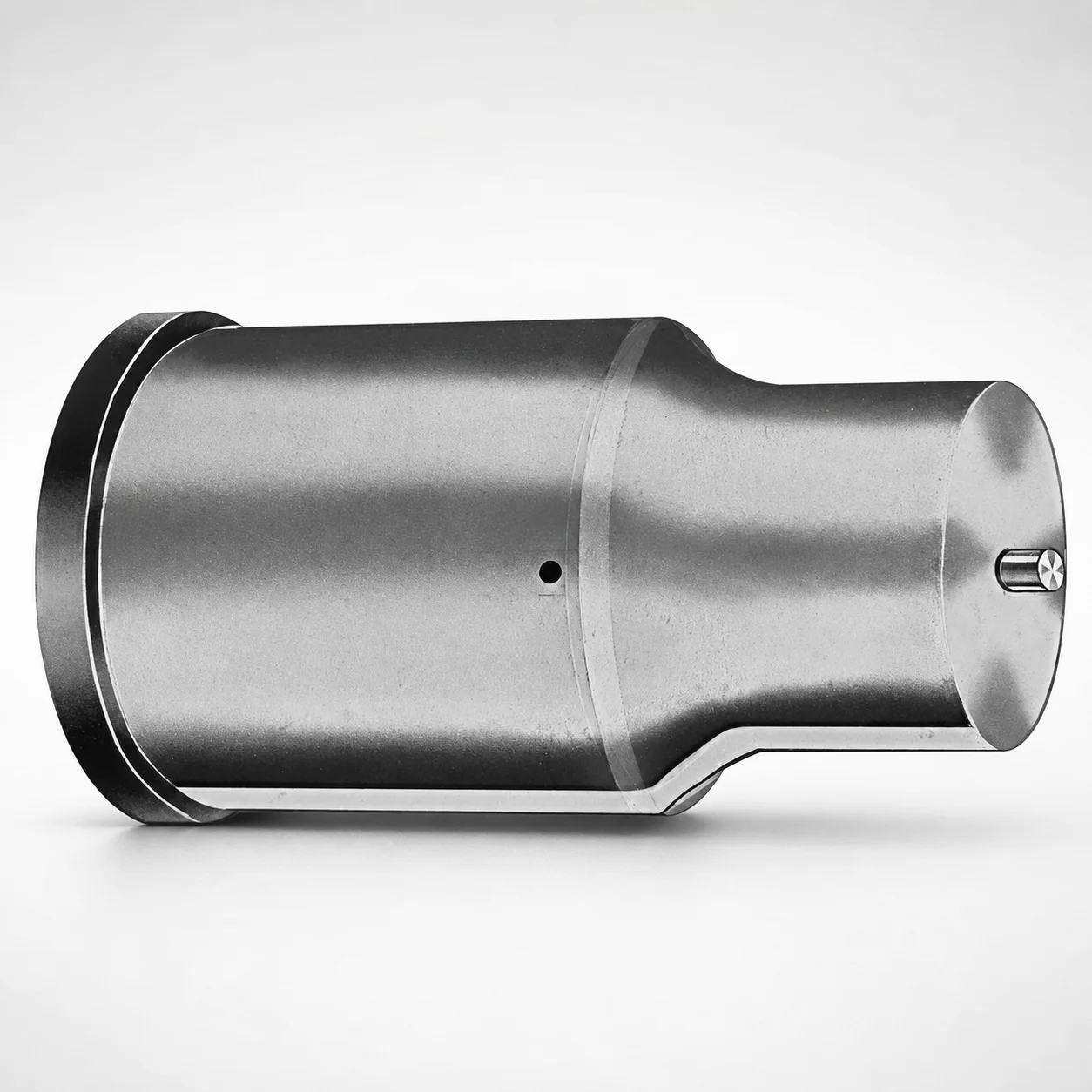
Extended Range Metric Ejector Punches XCDP Coating
Extended Range Metric ejector punches (XCDP coating) are engineered for longer-stroke ejection needs in precision die and mold assemblies, combining smooth punch performance with reliable surface protection for production.
- Extended-range geometry supports longer ejection travel in compact mold layouts
- XCDP coating helps reduce wear and friction for stable punch life
- Optional tip and shank geometries (X, R, K, O, and more) for application fit
- Metric build simplifies sourcing and compatibility for standard punch tooling
Specifications
50 configurations available
| Tip shape | D (Shank dia.) (mm) | L1 (Point Length) (mm) | L (Length) (mm) | P Dimension (mm) | W Dimension (mm) | R Dimension (mm) |
|---|---|---|---|---|---|---|
| H | 40 | 25 ~ 30 | 63 ~ 100 | 20 ~ 39.95 | 8 ~ 39.95 | - |
| H | 45 | 25 ~ 30 | 63 ~ 100 | 25 ~ 44.95 | 9 ~ 44.95 | - |
| H | 50 | 25 ~ 30 | 63 ~ 100 | 30 ~ 49.95 | 10 ~ 49.95 | - |
| H | 56 | 25 ~ 30 | 63 ~ 100 | 35 ~ 55.95 | 11 ~ 55.95 | - |
| H | 63 | 25 ~ 30 | 63 ~ 100 | 40 ~ 62.95 | 12 ~ 62.95 | - |
| J | 40 | 25 ~ 30 | 63 ~ 100 | 20 ~ 39.95 | 8 ~ 39.95 | - |
| J | 45 | 25 ~ 30 | 63 ~ 100 | 25 ~ 44.95 | 9 ~ 44.95 | - |
| J | 50 | 25 ~ 30 | 63 ~ 100 | 30 ~ 49.95 | 10 ~ 49.95 | - |
| J | 56 | 25 ~ 30 | 63 ~ 100 | 35 ~ 55.95 | 11 ~ 55.95 | - |
| J | 63 | 25 ~ 30 | 63 ~ 100 | 40 ~ 62.95 | 12 ~ 62.95 | - |
| K | 40 | 25 ~ 30 | 63 ~ 100 | 20 ~ 39.95 | 8 ~ 39.95 | 0.2 ~ 19.975 |
| K | 45 | 25 ~ 30 | 63 ~ 100 | 25 ~ 44.95 | 9 ~ 44.95 | 0.2 ~ 22.475 |
| K | 50 | 25 ~ 30 | 63 ~ 100 | 30 ~ 49.95 | 10 ~ 49.95 | 0.2 ~ 24.975 |
| K | 56 | 25 ~ 30 | 63 ~ 100 | 35 ~ 55.95 | 11 ~ 55.95 | 0.2 ~ 27.975 |
| K | 63 | 25 ~ 30 | 63 ~ 100 | 40 ~ 62.95 | 12 ~ 62.95 | 0.2 ~ 31.475 |
| N | 40 | 25 ~ 30 | 63 ~ 100 | - | 8 ~ 39.95 | - |
| N | 45 | 25 ~ 30 | 63 ~ 100 | - | 9 ~ 44.95 | - |
| N | 50 | 25 ~ 30 | 63 ~ 100 | - | 10 ~ 49.95 | - |
| N | 56 | 25 ~ 30 | 63 ~ 100 | - | 11 ~ 55.95 | - |
| N | 63 | 25 ~ 30 | 63 ~ 100 | - | 12 ~ 62.95 | - |
| O | 40 | 25 ~ 30 | 63 ~ 100 | 20 ~ 39.95 | 8 ~ 39.95 | - |
| O | 45 | 25 ~ 30 | 63 ~ 100 | 25 ~ 44.95 | 9 ~ 44.95 | - |
| O | 50 | 25 ~ 30 | 63 ~ 100 | 30 ~ 49.95 | 10 ~ 49.95 | - |
| O | 56 | 25 ~ 30 | 63 ~ 100 | 35 ~ 55.95 | 11 ~ 55.95 | - |
| O | 63 | 25 ~ 30 | 63 ~ 100 | 40 ~ 62.95 | 12 ~ 62.95 | - |
| R | 40 | 25 ~ 30 | 63 ~ 100 | 20 ~ 39.95 | 8 ~ 39.95 | - |
| R | 45 | 25 ~ 30 | 63 ~ 100 | 25 ~ 44.95 | 9 ~ 44.95 | - |
| R | 50 | 25 ~ 30 | 63 ~ 100 | 30 ~ 49.95 | 10 ~ 49.95 | - |
| R | 56 | 25 ~ 30 | 63 ~ 100 | 35 ~ 55.95 | 11 ~ 55.95 | - |
| R | 63 | 25 ~ 30 | 63 ~ 100 | 40 ~ 62.95 | 12 ~ 62.95 | - |
| V | 40 | 25 ~ 30 | 63 ~ 100 | 20 ~ 39.95 | 8 ~ 39.95 | - |
| V | 45 | 25 ~ 30 | 63 ~ 100 | 25 ~ 44.95 | 9 ~ 44.95 | - |
| V | 50 | 25 ~ 30 | 63 ~ 100 | 30 ~ 49.95 | 10 ~ 49.95 | - |
| V | 56 | 25 ~ 30 | 63 ~ 100 | 35 ~ 55.95 | 11 ~ 55.95 | - |
| V | 63 | 25 ~ 30 | 63 ~ 100 | 40 ~ 62.95 | 12 ~ 62.95 | - |
| X | 40 | 25 ~ 30 | 63 ~ 100 | 20 ~ 39.95 | - | - |
| X | 45 | 25 ~ 30 | 63 ~ 100 | 25 ~ 44.95 | - | - |
| X | 50 | 25 ~ 30 | 63 ~ 100 | 30 ~ 49.95 | - | - |
| X | 56 | 25 ~ 30 | 63 ~ 100 | 35 ~ 55.95 | - | - |
| X | 63 | 25 ~ 30 | 63 ~ 100 | 40 ~ 62.95 | - | - |
| Y | 40 | 25 ~ 30 | 63 ~ 100 | 20 ~ 39.95 | 8 ~ 39.95 | 0.2 ~ 19.975 |
| Y | 45 | 25 ~ 30 | 63 ~ 100 | 25 ~ 44.95 | 9 ~ 44.95 | 0.2 ~ 22.475 |
| Y | 50 | 25 ~ 30 | 63 ~ 100 | 30 ~ 49.95 | 10 ~ 49.95 | 0.2 ~ 24.975 |
| Y | 56 | 25 ~ 30 | 63 ~ 100 | 35 ~ 55.95 | 11 ~ 55.95 | 0.2 ~ 27.975 |
| Y | 63 | 25 ~ 30 | 63 ~ 100 | 40 ~ 62.95 | 12 ~ 62.95 | 0.2 ~ 31.475 |
| Z | 40 | 25 ~ 30 | 63 ~ 100 | - | 8 ~ 39.95 | 0.2 ~ 19.975 |
| Z | 45 | 25 ~ 30 | 63 ~ 100 | - | 9 ~ 44.95 | 0.2 ~ 22.475 |
| Z | 50 | 25 ~ 30 | 63 ~ 100 | - | 10 ~ 49.95 | 0.2 ~ 24.975 |
| Z | 56 | 25 ~ 30 | 63 ~ 100 | - | 11 ~ 55.95 | 0.2 ~ 27.975 |
| Z | 63 | 25 ~ 30 | 63 ~ 100 | - | 12 ~ 62.95 | 0.2 ~ 31.475 |
Product Guide
Application Scenarios+
Extended stroke ejection in precision die and mold assemblies often demands stable punch movement over a longer travel distance than standard punches can provide. This variant’s extended-range geometry is suited for longer ejection travel in compact layouts, helping maintain consistent alignment during cycling.
In automotive interior/exterior trim and connector subassemblies, these punches are commonly used where tight packaging forces longer ejection distance. The durable XCDP surface coating supports reduced wear and friction, which helps preserve punch precision under high cycle counts.
For appliance and industrial housing parts molded with textured or thicker-wall features, controlled ejection reduces risk of surface marking and deformation. The ability to select from multiple tip shapes (H, J, K, N, O, R, V, X, Y, Z) allows engineers to match contact geometry to part stiffness and ejection force distribution.
Material & Process Details+
The specific base steel grade and exact heat treatment state are not provided in the supplied data. What can be stated is that the punch is engineered with an XCDP coating to improve surface protection during sliding contact in the guide system and at the ejection interface.
XCDP coating benefits for mold tooling include:
- Wear resistance to extend usable punch life under repetitive ejection cycles
- Lower friction to reduce stick-slip behavior and maintain smoother punch travel
- Improved surface stability that supports consistent dimensional performance over time
Because hardness (e.g., HRC), substrate toughness, and any post-processing (such as nitriding or quenching/tempering) are not specified here, material-property comparisons across alternative steels cannot be confirmed from the current inputs.
Sizing & Selection Guide+
Use the listed ranges to match this extended-range metric punch to your cavity/core ejection requirements. The overall length (L) is fixed at 63 to 100 mm, which should be checked against your ejector plate thickness and required stroke envelope.
The point length (L1) is fixed at 25 to 30 mm. Select this to ensure the point engages the part sufficiently without bottoming against the cavity/core.
- Shank diameter (D): choose from 40, 45, 50, 56, 63 mm to fit your guide bore and maintain proper guidance.
- P dimension: select within 20–39.95, 25–44.95, 30–49.95, 35–55.95, or 40–62.95 mm based on required spacing/positioning to the ejector interface.
- W dimension: select within 8–39.95, 9–44.95, 10–49.95, 11–55.95, or 12–62.95 mm to match the local geometry constraints.
- R dimension: use 0.2–19.975 up to 0.2–31.475 mm for the required corner/edge form.
Tip shape selection (H, J, K, N, O, R, V, X, Y, Z) should be driven by contact pressure needs. Tolerance/fit values are not included in the provided data, so confirm critical clearances (D vs. guide bore) with your mold’s drawing standards.
Frequently Asked Questions
How do I choose the correct shank diameter (D) for guide fit in extended-stroke molds?+
What parts of the geometry determine the engagement depth and ejection travel for these punches?+
Which tip shapes are available, and how should I select one for part ejection reliability?+
What does the XCDP coating help with in production, and what material property data is provided?+
How do I match the configurable R dimension to avoid stress concentration at the punch tip?+
Related Products






Need Custom Specifications?
Our engineering team can help with custom configurations, material selection, and volume pricing.