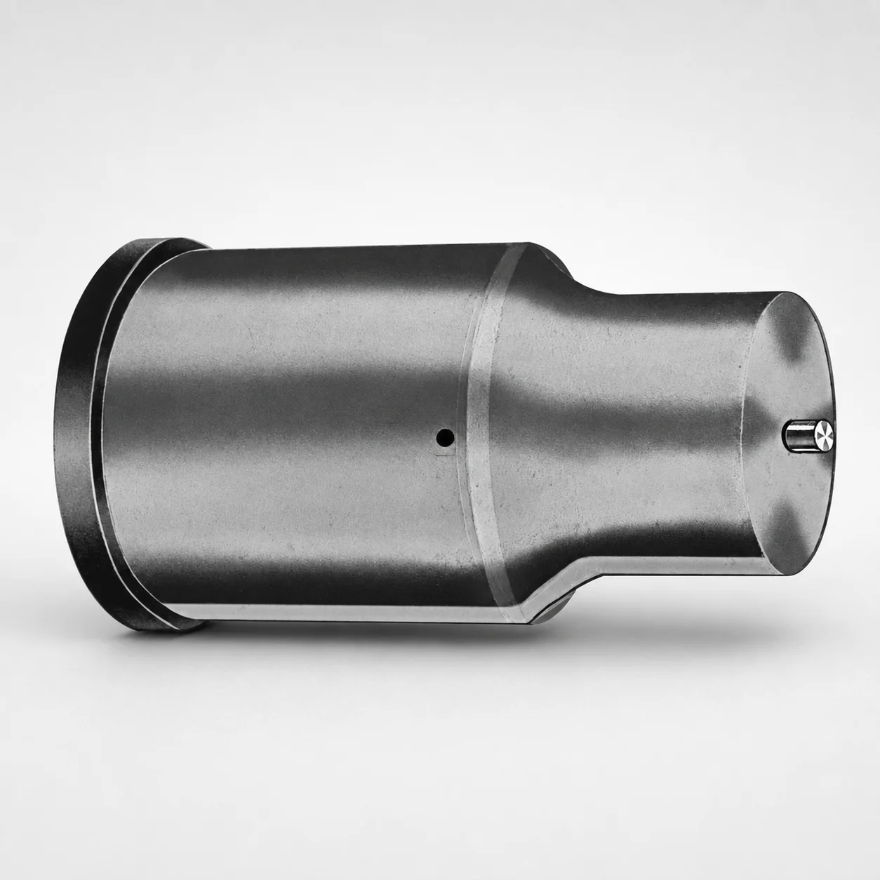
Extended Range Ejector Punches (Metric, XNA Coating)
Extended Range Ejector Punches (Metric, XNA Coating) are designed for consistent ejection performance in deep-mold or long-reach applications. The XNA coated surface helps reduce friction and wear for stable operation.
- Extended reach punch format supports ejection from deeper cavities
- XNA coating improves sliding wear resistance during molding cycles
- Selectable tip geometry for fit in different ejection layouts and clearances
- Metric punch body range for broad tooling compatibility in industrial molds
Specifications
50 configurations available
| Tip shape | D (Shank dia.) (mm) | L1 (Point Length) (mm) | L (Length) (mm) | P Dimension (mm) | W Dimension (mm) | R Dimension (mm) |
|---|---|---|---|---|---|---|
| H | 40 | 25 ~ 30 | 63 ~ 100 | 20 ~ 39.95 | 8 ~ 39.95 | - |
| H | 45 | 25 ~ 30 | 63 ~ 100 | 25 ~ 44.95 | 9 ~ 44.95 | - |
| H | 50 | 25 ~ 30 | 63 ~ 100 | 30 ~ 49.95 | 10 ~ 49.95 | - |
| H | 56 | 25 ~ 30 | 63 ~ 100 | 35 ~ 55.95 | 11 ~ 55.95 | - |
| H | 63 | 25 ~ 30 | 63 ~ 100 | 40 ~ 62.95 | 12 ~ 62.95 | - |
| J | 40 | 25 ~ 30 | 63 ~ 100 | 20 ~ 39.95 | 8 ~ 39.95 | - |
| J | 45 | 25 ~ 30 | 63 ~ 100 | 25 ~ 44.95 | 9 ~ 44.95 | - |
| J | 50 | 25 ~ 30 | 63 ~ 100 | 30 ~ 49.95 | 10 ~ 49.95 | - |
| J | 56 | 25 ~ 30 | 63 ~ 100 | 35 ~ 55.95 | 11 ~ 55.95 | - |
| J | 63 | 25 ~ 30 | 63 ~ 100 | 40 ~ 62.95 | 12 ~ 62.95 | - |
| K | 40 | 25 ~ 30 | 63 ~ 100 | 20 ~ 39.95 | 8 ~ 39.95 | 0.2 ~ 19.975 |
| K | 45 | 25 ~ 30 | 63 ~ 100 | 25 ~ 44.95 | 9 ~ 44.95 | 0.2 ~ 22.475 |
| K | 50 | 25 ~ 30 | 63 ~ 100 | 30 ~ 49.95 | 10 ~ 49.95 | 0.2 ~ 24.975 |
| K | 56 | 25 ~ 30 | 63 ~ 100 | 35 ~ 55.95 | 11 ~ 55.95 | 0.2 ~ 27.975 |
| K | 63 | 25 ~ 30 | 63 ~ 100 | 40 ~ 62.95 | 12 ~ 62.95 | 0.2 ~ 31.475 |
| N | 40 | 25 ~ 30 | 63 ~ 100 | - | 8 ~ 39.95 | - |
| N | 45 | 25 ~ 30 | 63 ~ 100 | - | 9 ~ 44.95 | - |
| N | 50 | 25 ~ 30 | 63 ~ 100 | - | 10 ~ 49.95 | - |
| N | 56 | 25 ~ 30 | 63 ~ 100 | - | 11 ~ 55.95 | - |
| N | 63 | 25 ~ 30 | 63 ~ 100 | - | 12 ~ 62.95 | - |
| O | 40 | 25 ~ 30 | 63 ~ 100 | 20 ~ 39.95 | 8 ~ 39.95 | - |
| O | 45 | 25 ~ 30 | 63 ~ 100 | 25 ~ 44.95 | 9 ~ 44.95 | - |
| O | 50 | 25 ~ 30 | 63 ~ 100 | 30 ~ 49.95 | 10 ~ 49.95 | - |
| O | 56 | 25 ~ 30 | 63 ~ 100 | 35 ~ 55.95 | 11 ~ 55.95 | - |
| O | 63 | 25 ~ 30 | 63 ~ 100 | 40 ~ 62.95 | 12 ~ 62.95 | - |
| R | 40 | 25 ~ 30 | 63 ~ 100 | 20 ~ 39.95 | 8 ~ 39.95 | - |
| R | 45 | 25 ~ 30 | 63 ~ 100 | 25 ~ 44.95 | 9 ~ 44.95 | - |
| R | 50 | 25 ~ 30 | 63 ~ 100 | 30 ~ 49.95 | 10 ~ 49.95 | - |
| R | 56 | 25 ~ 30 | 63 ~ 100 | 35 ~ 55.95 | 11 ~ 55.95 | - |
| R | 63 | 25 ~ 30 | 63 ~ 100 | 40 ~ 62.95 | 12 ~ 62.95 | - |
| V | 40 | 25 ~ 30 | 63 ~ 100 | 20 ~ 39.95 | 8 ~ 39.95 | - |
| V | 45 | 25 ~ 30 | 63 ~ 100 | 25 ~ 44.95 | 9 ~ 44.95 | - |
| V | 50 | 25 ~ 30 | 63 ~ 100 | 30 ~ 49.95 | 10 ~ 49.95 | - |
| V | 56 | 25 ~ 30 | 63 ~ 100 | 35 ~ 55.95 | 11 ~ 55.95 | - |
| V | 63 | 25 ~ 30 | 63 ~ 100 | 40 ~ 62.95 | 12 ~ 62.95 | - |
| X | 40 | 25 ~ 30 | 63 ~ 100 | 20 ~ 39.95 | - | - |
| X | 45 | 25 ~ 30 | 63 ~ 100 | 25 ~ 44.95 | - | - |
| X | 50 | 25 ~ 30 | 63 ~ 100 | 30 ~ 49.95 | - | - |
| X | 56 | 25 ~ 30 | 63 ~ 100 | 35 ~ 55.95 | - | - |
| X | 63 | 25 ~ 30 | 63 ~ 100 | 40 ~ 62.95 | - | - |
| Y | 40 | 25 ~ 30 | 63 ~ 100 | 20 ~ 39.95 | 8 ~ 39.95 | 0.2 ~ 19.975 |
| Y | 45 | 25 ~ 30 | 63 ~ 100 | 25 ~ 44.95 | 9 ~ 44.95 | 0.2 ~ 22.475 |
| Y | 50 | 25 ~ 30 | 63 ~ 100 | 30 ~ 49.95 | 10 ~ 49.95 | 0.2 ~ 24.975 |
| Y | 56 | 25 ~ 30 | 63 ~ 100 | 35 ~ 55.95 | 11 ~ 55.95 | 0.2 ~ 27.975 |
| Y | 63 | 25 ~ 30 | 63 ~ 100 | 40 ~ 62.95 | 12 ~ 62.95 | 0.2 ~ 31.475 |
| Z | 40 | 25 ~ 30 | 63 ~ 100 | - | 8 ~ 39.95 | 0.2 ~ 19.975 |
| Z | 45 | 25 ~ 30 | 63 ~ 100 | - | 9 ~ 44.95 | 0.2 ~ 22.475 |
| Z | 50 | 25 ~ 30 | 63 ~ 100 | - | 10 ~ 49.95 | 0.2 ~ 24.975 |
| Z | 56 | 25 ~ 30 | 63 ~ 100 | - | 11 ~ 55.95 | 0.2 ~ 27.975 |
| Z | 63 | 25 ~ 30 | 63 ~ 100 | - | 12 ~ 62.95 | 0.2 ~ 31.475 |
Product Guide
Application Scenarios+
Extended-range ejector punches are used in injection mold tooling where parts must be released from deep cavities or long-reach gate regions without sticking. In deep automotive connector housings and interior lamp supports, the extended reach helps maintain stable ejection travel while the XNA coated sliding surface reduces friction during repeated cycles.
They are also suitable for medical device housings and precision electronics clips where consistent ejection force is needed to avoid surface marring. The XNA coating supports wear resistance at the ejector-to-bush interface, helping preserve alignment over the tool’s service life.
For large appliance housings and thick-walled casings, engineers can match the point length and selectable tip shapes (H, J, K, N, O, R, V, X, Y, Z) to local geometry and clearance constraints, improving contact reliability across varying ejection layouts.
Material & Process Details+
The provided specification set identifies an XNA coated ejector punch variant, where the coating is the key functional improvement for mold reliability under high sliding contact. While the base steel grade and exact heat-treatment cycle are not specified in the available data, the intended performance target is lower coefficient of friction and improved resistance to adhesive and abrasive wear during continuous molding.
In practice, ejector punch steels are typically balanced between hardness (for wear resistance) and toughness (for impact and bending resistance). Higher surface hardness generally increases abrasion resistance but can reduce toughness if not properly heat treated; therefore, tools often use quenched & tempered or similar hardening approaches to maintain a stable combination of wear life and ductility.
- XNA coating: improves sliding wear resistance and reduces frictional galling risk at the guide interface.
- Trade-off: increased surface protection supports longer life, but proper clearance and alignment are still required to prevent bending stress.
Sizing & Selection Guide+
Select an extended-range ejector punch by matching the required ejection travel and working tip geometry to the mold core/cavity layout. Use the fixed dimensions first: L1 (point length) = 25–30 mm and L (overall length) = 63–100 mm, ensuring the punch can reach the part contact zone while maintaining sufficient support length inside the ejector guide.
Then choose D (shank diameter) = 40, 45, 50, 56, or 63 mm to suit the guide bore/bushing sizing and to control lateral stiffness. Match the P and W dimensions to your layout’s spacing and clearance requirements, using the available ranges (P: 20–39.95, 25–44.95, 30–49.95, 35–55.95, 40–62.95 mm; W: 8–39.95, 9–44.95, 10–49.95, 11–55.95, 12–62.95 mm). The selectable R range (0.2–19.975, 0.2–22.475, 0.2–24.975, 0.2–27.975, 0.2–31.475 mm) supports adapting corner radii to reduce stress concentration and improve contact consistency.
- Tip shape: select H/J/K/N/O/R/V/X/Y/Z to fit local ejection contact geometry.
- Tolerance/fit: confirm guide and bushing clearance in your standard—XNA coating reduces friction but does not replace mechanical alignment requirements.
Frequently Asked Questions
Which tip shapes (H, J, K, N, O, R, V, X, Y, Z) should I choose for reliable part contact in an extended ejection design?+
Use the available tip shape options (H, J, K, N, O, R, V, X, Y, Z) based on the part contact area and clearance in your ejection layout. Select the shape that maximizes stable contact within the required L1 = 25–30 mm working point length. If your mold has tight corners or ribs, consider shapes aligned to your chosen R range for better geometry match.
How do I match the punch length to deep-cavity ejection needs using L1 and L?+
Start by setting L1 (point length) = 25–30 mm to cover the distance from the ejector interface to the actual part contact zone. Then verify L (overall length) = 63–100 mm provides enough reach while keeping adequate support inside the guide/bushing system. For deeper cavities, you typically move toward the upper end of the L range while maintaining safe contact and alignment.
What shank diameter (D) options are available, and how do they affect stiffness and guide sizing?+
This series provides D (shank dia.) in 40, 45, 50, 56, 63 mm. Choose D to match the guide/bushing bore and to achieve the stiffness required to prevent bending during ejection. Larger D generally increases lateral stiffness, but it must be compatible with your existing guide and layout constraints.
How should I use the P, W, and R dimension ranges when designing the ejector layout?+
Use P and W to fit your layout spacing and clearance—select the variant whose ranges match your required geometry (P: 20–39.95 up to 40–62.95; W: 8–39.95 up to 12–62.95). Then choose an R value in the provided range (0.2–19.975 up to 0.2–31.475) to align corner radii with your part and reduce stress concentration at contact.
What does the XNA coating contribute for wear and friction at the ejector guide interface?+
The XNA coating is included to improve performance in repeated molding cycles by reducing sliding friction and enhancing wear resistance at the ejector-to-guide interface. In extended-range applications where sliding distance and contact time are higher, this can help preserve consistent motion and reduce coating-related galling risk. Ensure your guide clearance and alignment are still engineered correctly since coating cannot compensate for misfit.
Related Products






Need Custom Specifications?
Our engineering team can help with custom configurations, material selection, and volume pricing.