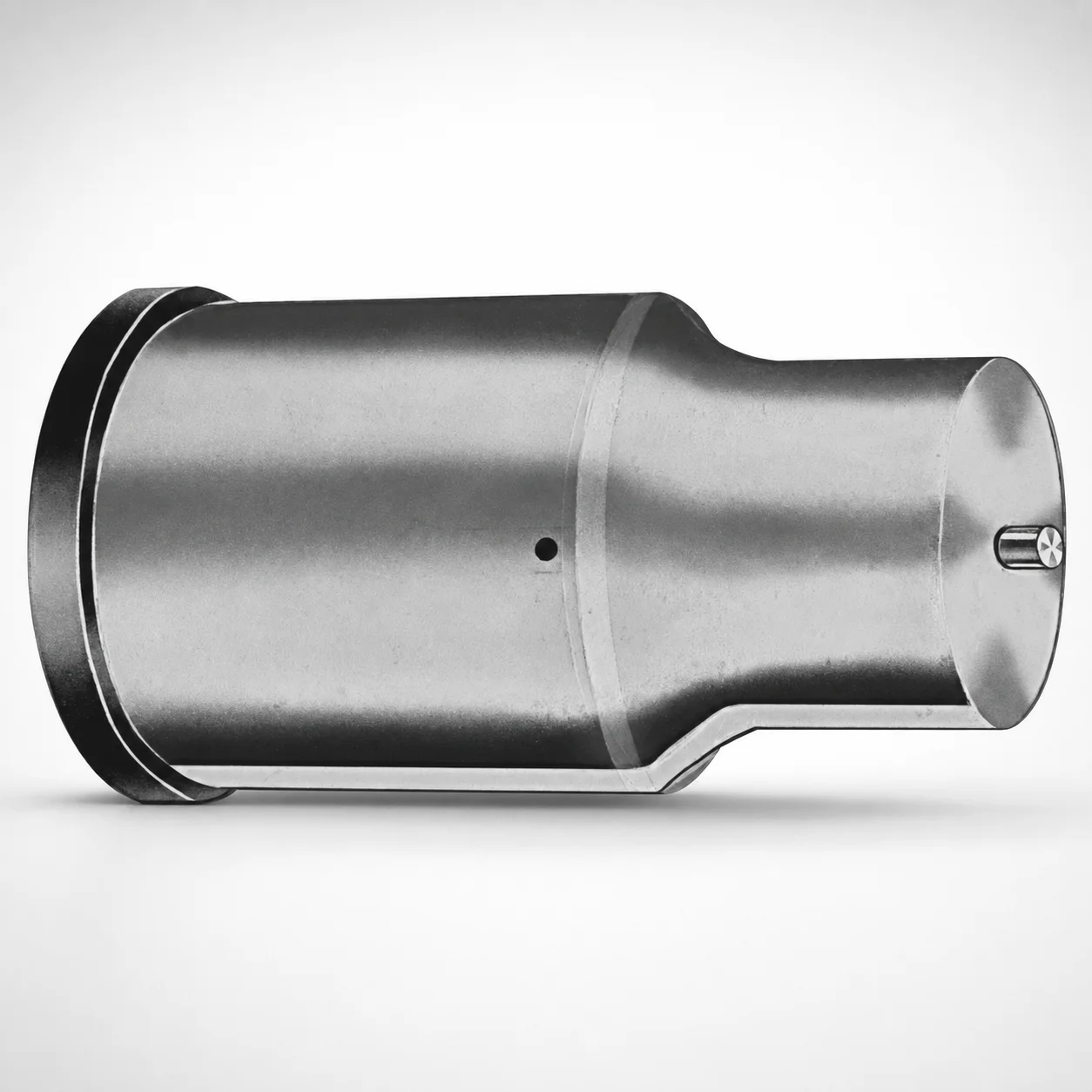
CRN Coated Extended Range Ejector Punches - Metric
Extended Range Ejector Punches - Metric (CRN coated) are engineered for deep stroke ejection in progressive dies, transfer tools, and general tooling where stable punch guidance matters. The CRN surface coating helps reduce friction and wear to support reliable production cycles.
- Extended range punch geometry for dependable ejection across long stroke lengths
- CRN coating improves wear resistance and reduces galling during cycling
- Hardened tool steel build supports consistent punch alignment under load
- Built for die maintenance workflows requiring repeatable performance in metric tooling
Specifications
50 configurations available
| Tip shape | D (Shank dia.) (mm) | L1 (Point Length) (mm) | L (Length) (mm) | P Dimension (mm) | W Dimension (mm) | R Dimension (mm) |
|---|---|---|---|---|---|---|
| H | 40 | 25 ~ 30 | 63 ~ 100 | 20 ~ 39.95 | 8 ~ 39.95 | - |
| H | 45 | 25 ~ 30 | 63 ~ 100 | 25 ~ 44.95 | 9 ~ 44.95 | - |
| H | 50 | 25 ~ 30 | 63 ~ 100 | 30 ~ 49.95 | 10 ~ 49.95 | - |
| H | 56 | 25 ~ 30 | 63 ~ 100 | 35 ~ 55.95 | 11 ~ 55.95 | - |
| H | 63 | 25 ~ 30 | 63 ~ 100 | 40 ~ 62.95 | 12 ~ 62.95 | - |
| J | 40 | 25 ~ 30 | 63 ~ 100 | 20 ~ 39.95 | 8 ~ 39.95 | - |
| J | 45 | 25 ~ 30 | 63 ~ 100 | 25 ~ 44.95 | 9 ~ 44.95 | - |
| J | 50 | 25 ~ 30 | 63 ~ 100 | 30 ~ 49.95 | 10 ~ 49.95 | - |
| J | 56 | 25 ~ 30 | 63 ~ 100 | 35 ~ 55.95 | 11 ~ 55.95 | - |
| J | 63 | 25 ~ 30 | 63 ~ 100 | 40 ~ 62.95 | 12 ~ 62.95 | - |
| K | 40 | 25 ~ 30 | 63 ~ 100 | 20 ~ 39.95 | 8 ~ 39.95 | 0.2 ~ 19.975 |
| K | 45 | 25 ~ 30 | 63 ~ 100 | 25 ~ 44.95 | 9 ~ 44.95 | 0.2 ~ 22.475 |
| K | 50 | 25 ~ 30 | 63 ~ 100 | 30 ~ 49.95 | 10 ~ 49.95 | 0.2 ~ 24.975 |
| K | 56 | 25 ~ 30 | 63 ~ 100 | 35 ~ 55.95 | 11 ~ 55.95 | 0.2 ~ 27.975 |
| K | 63 | 25 ~ 30 | 63 ~ 100 | 40 ~ 62.95 | 12 ~ 62.95 | 0.2 ~ 31.475 |
| N | 40 | 25 ~ 30 | 63 ~ 100 | - | 8 ~ 39.95 | - |
| N | 45 | 25 ~ 30 | 63 ~ 100 | - | 9 ~ 44.95 | - |
| N | 50 | 25 ~ 30 | 63 ~ 100 | - | 10 ~ 49.95 | - |
| N | 56 | 25 ~ 30 | 63 ~ 100 | - | 11 ~ 55.95 | - |
| N | 63 | 25 ~ 30 | 63 ~ 100 | - | 12 ~ 62.95 | - |
| O | 40 | 25 ~ 30 | 63 ~ 100 | 20 ~ 39.95 | 8 ~ 39.95 | - |
| O | 45 | 25 ~ 30 | 63 ~ 100 | 25 ~ 44.95 | 9 ~ 44.95 | - |
| O | 50 | 25 ~ 30 | 63 ~ 100 | 30 ~ 49.95 | 10 ~ 49.95 | - |
| O | 56 | 25 ~ 30 | 63 ~ 100 | 35 ~ 55.95 | 11 ~ 55.95 | - |
| O | 63 | 25 ~ 30 | 63 ~ 100 | 40 ~ 62.95 | 12 ~ 62.95 | - |
| R | 40 | 25 ~ 30 | 63 ~ 100 | 20 ~ 39.95 | 8 ~ 39.95 | - |
| R | 45 | 25 ~ 30 | 63 ~ 100 | 25 ~ 44.95 | 9 ~ 44.95 | - |
| R | 50 | 25 ~ 30 | 63 ~ 100 | 30 ~ 49.95 | 10 ~ 49.95 | - |
| R | 56 | 25 ~ 30 | 63 ~ 100 | 35 ~ 55.95 | 11 ~ 55.95 | - |
| R | 63 | 25 ~ 30 | 63 ~ 100 | 40 ~ 62.95 | 12 ~ 62.95 | - |
| V | 40 | 25 ~ 30 | 63 ~ 100 | 20 ~ 39.95 | 8 ~ 39.95 | - |
| V | 45 | 25 ~ 30 | 63 ~ 100 | 25 ~ 44.95 | 9 ~ 44.95 | - |
| V | 50 | 25 ~ 30 | 63 ~ 100 | 30 ~ 49.95 | 10 ~ 49.95 | - |
| V | 56 | 25 ~ 30 | 63 ~ 100 | 35 ~ 55.95 | 11 ~ 55.95 | - |
| V | 63 | 25 ~ 30 | 63 ~ 100 | 40 ~ 62.95 | 12 ~ 62.95 | - |
| X | 40 | 25 ~ 30 | 63 ~ 100 | 20 ~ 39.95 | - | - |
| X | 45 | 25 ~ 30 | 63 ~ 100 | 25 ~ 44.95 | - | - |
| X | 50 | 25 ~ 30 | 63 ~ 100 | 30 ~ 49.95 | - | - |
| X | 56 | 25 ~ 30 | 63 ~ 100 | 35 ~ 55.95 | - | - |
| X | 63 | 25 ~ 30 | 63 ~ 100 | 40 ~ 62.95 | - | - |
| Y | 40 | 25 ~ 30 | 63 ~ 100 | 20 ~ 39.95 | 8 ~ 39.95 | 0.2 ~ 19.975 |
| Y | 45 | 25 ~ 30 | 63 ~ 100 | 25 ~ 44.95 | 9 ~ 44.95 | 0.2 ~ 22.475 |
| Y | 50 | 25 ~ 30 | 63 ~ 100 | 30 ~ 49.95 | 10 ~ 49.95 | 0.2 ~ 24.975 |
| Y | 56 | 25 ~ 30 | 63 ~ 100 | 35 ~ 55.95 | 11 ~ 55.95 | 0.2 ~ 27.975 |
| Y | 63 | 25 ~ 30 | 63 ~ 100 | 40 ~ 62.95 | 12 ~ 62.95 | 0.2 ~ 31.475 |
| Z | 40 | 25 ~ 30 | 63 ~ 100 | - | 8 ~ 39.95 | 0.2 ~ 19.975 |
| Z | 45 | 25 ~ 30 | 63 ~ 100 | - | 9 ~ 44.95 | 0.2 ~ 22.475 |
| Z | 50 | 25 ~ 30 | 63 ~ 100 | - | 10 ~ 49.95 | 0.2 ~ 24.975 |
| Z | 56 | 25 ~ 30 | 63 ~ 100 | - | 11 ~ 55.95 | 0.2 ~ 27.975 |
| Z | 63 | 25 ~ 30 | 63 ~ 100 | - | 12 ~ 62.95 | 0.2 ~ 31.475 |
Product Guide
Application Scenarios+
Extended stroke ejection is critical in progressive die and transfer tooling where part geometry requires longer punch travel to fully release from the cavity. These metric ejector punches use an extended-range geometry and a CRN coating to support stable guidance and consistent cycling over long stroke lengths.
- For automotive and appliance stamping, the long punch length helps maintain positive ejection while the hardened tool-steel body resists alignment shift under repetitive load.
- In die casting die maintenance and core knock-out, the CRN surface helps reduce friction and galling at the sliding interface, improving repeatability during high-cycle production.
- For general fabrication tooling with deeper or taller components, choose this variant when you need reliable ejection with controlled wear to maintain dimensional stability over time.
Material & Process Details+
This product is built from toughened tool steel (as specified in the description) to provide strong punch guidance and load-bearing stability for extended strokes. The CRN (chromium nitride) coating is applied to the working surfaces to improve wear resistance and lower friction, helping mitigate galling during continuous ejection cycles.
- Heat treatment state: hardened tool steel (per product description) to balance stiffness and toughness for guided ejection.
- Hardness & wear/toughness trade-off: the hardened base increases wear resistance and dimensional stability, while the tool-steel toughness supports repeated impact forces during part ejection.
- Wear performance: CRN coating reduces surface damage mechanisms that can develop under sliding contact and high cycling.
If you compare variants with different coatings, CRN is typically selected specifically for reduced friction and improved galling resistance under production wear conditions; the hardened tool-steel core maintains alignment under load.
Sizing & Selection Guide+
Select dimensions by matching the punch’s stroke travel and guidance envelope to the die or transfer tool’s core/cavity geometry. This metric extended-range series offers a fixed point length (L1) of 25–30 mm and a fixed overall length (L) of 63–100 mm, which should be chosen to cover the required ejection travel while maintaining safe engagement and clearance.
- Shank diameter (D): choose one of 40, 45, 50, 56, 63 mm based on the holder bore and guidance requirements.
- Interface geometry: select the matching P dimension (20–39.95, 25–44.95, 30–49.95, 35–55.95, 40–62.95 mm) and W dimension (8–39.95, 9–44.95, 10–49.95, 11–55.95, 12–62.95 mm) to fit the specific mating die pocket features.
- Tip radius (R): range 0.2–19.975, 0.2–22.475, 0.2–24.975, 0.2–27.975, 0.2–31.475 mm should be selected to match part surface needs and reduce stress concentration.
For fit, confirm that the chosen D supports the guidance bore clearance after coating (CRN) and that the tip geometry (H/J/K/N/O/R/V/X/Y/Z) does not interfere with cavity land features.
Frequently Asked Questions
Which tip shapes (H, J, K, N, O, R, V, X, Y, Z) are appropriate for deeper ejection in progressive dies?+
Tip shape selection should be based on part geometry and the required contact pattern at the ejection interface. This series supports multiple metric tip shapes H, J, K, N, O, R, V, X, Y, Z, allowing you to match the punch end to the cavity surface without changing the extended-range length coverage.
When designing for deeper strokes, prioritize correct overall length L (63–100 mm) and point length L1 (25–30 mm) so the tip remains properly engaged throughout ejection.
How do I choose shank diameter D (40/45/50/56/63 mm) for stable guidance?+
Choose D based on the die or guide holder bore that controls punch alignment. The available shank diameter options are 40, 45, 50, 56, 63 mm, so you can match common holder sizing for guided ejection.
Because this punch uses a CRN coated surface, confirm clearance in the guidance bore to avoid excessive friction or binding during production cycling.
What matters most when matching L1 and L for long-stroke ejection (25–30 mm vs 63–100 mm)?+
The point length L1 (25–30 mm) defines how far the tip extends for part contact, while the overall length L (63–100 mm) determines whether the punch can cover the required travel. For deep ejection applications in progressive dies or transfer tools, selecting an adequate L helps maintain stable guidance through the full stroke.
Verify that the selected L1 and tip radius R do not conflict with cavity/core features during the full eject stroke.
How does the CRN coating help prevent wear and galling on extended-range punches?+
The CRN coating is designed to reduce friction and improve wear resistance at sliding contact points during repeated ejection. This helps limit galling that can develop when punch surfaces repeatedly rub against guide and surrounding die components.
Combined with the hardened tool-steel core (toughened tool steel, per product description), it supports stable punch alignment under load for high-cycle tooling.
How should I select P, W, and R dimensions to avoid interference at the tip and interface?+
Use the available ranges for P, W, and R to match the mating die pocket features and the required tip engagement. The series provides P ranges of 20–39.95, 25–44.95, 30–49.95, 35–55.95, and 40–62.95 mm, and W ranges of 8–39.95, 9–44.95, 10–49.95, 11–55.95, and 12–62.95 mm.
For tip contact and stress distribution, select R from 0.2–19.975 up to 0.2–31.475 mm based on the part surface profile and required clearance.
Related Products






Need Custom Specifications?
Our engineering team can help with custom configurations, material selection, and volume pricing.