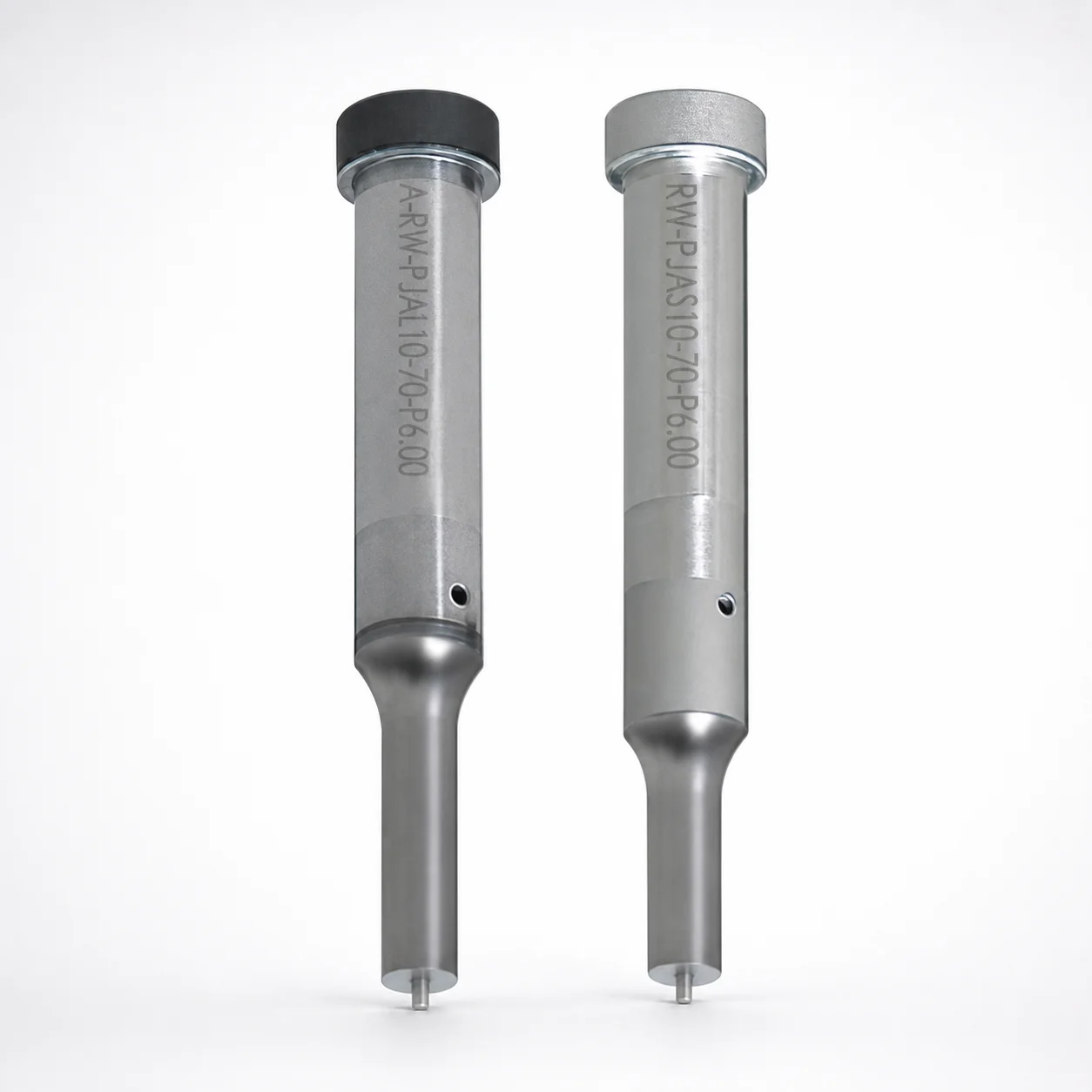
Ejector Punches - RW Coating SKH40 Steel
Ejector Punches - RW Coating SKH40 steel are designed for heavy-load tooling, using a single-stepped shank and a spring-reinforced ejector pin for reliable performance in punch-and-press operations.
- Single-stepped shank with spring-reinforced jector pin supports stable motion under load
- Built from SKH40-equivalent powdered high-speed steel for durability and consistent cutting action
- RW coating helps reduce friction and supports longer service life during repetitive cycles
- Suitable for die and mold punch use with multiple tip options, including round and rectangle
Specifications
4936 configurations available
| Jector | Tip shape | Shank diameter D tolerance | B (Tip length) | D (Shank diameter) (mm) | P (Tip dimension) (mm) | L (L dimension) (mm) | LC(Full length alteration) (mm) | LCT (Head thickness tolerance change + total length alteration) (mm) | LMT (Head thickness tolerance change + total length alteration) (mm) | PC (Tip dimension alteration) (mm) | R (Tip corner R) (mm) | W (Tip dimension) (mm) | WC (Tip dimension alteration) (mm) | type |
|---|---|---|---|---|---|---|---|---|---|---|---|---|---|---|
| Standard | Round | +0.005/0 | L | 4 | 1 ~ 3.99 | 50 ~ 80 | - | - | - | - | - | - | - | - |
| Standard | Round | +0.005/0 | L | 4 | - | 50 ~ 80 | - | - | - | 0.9 ~ 0.99 | - | - | - | - |
| Standard | Round | +0.005/0 | L | 4 | 1 ~ 3.99 | - | 39 ~ 79.9 | - | - | - | - | - | - | - |
| Standard | Round | +0.005/0 | L | 4 | - | - | 39 ~ 79.9 | - | - | 0.9 ~ 0.99 | - | - | - | - |
| Standard | Round | +0.005/0 | L | 4 | 1 ~ 3.99 | - | - | 39 ~ 79.9 | - | - | - | - | - | - |
| Standard | Round | +0.005/0 | L | 4 | - | - | - | 39 ~ 79.9 | - | 0.9 ~ 0.99 | - | - | - | - |
| Standard | Round | +0.005/0 | L | 4 | 1 ~ 3.99 | - | - | - | 39 ~ 79.9 | - | - | - | - | - |
| Standard | Round | +0.005/0 | L | 4 | - | - | - | - | 39 ~ 79.9 | 0.9 ~ 0.99 | - | - | - | - |
| Standard | Round | +0.005/0 | L | 5 | 2 ~ 4.99 | 50 ~ 80 | - | - | - | - | - | - | - | - |
| Standard | Round | +0.005/0 | L | 5 | - | 50 ~ 80 | - | - | - | 1.8 ~ 1.99 | - | - | - | - |
| Standard | Round | +0.005/0 | L | 5 | 2 ~ 4.99 | - | 39 ~ 79.9 | - | - | - | - | - | - | - |
| Standard | Round | +0.005/0 | L | 5 | - | - | 39 ~ 79.9 | - | - | 1.8 ~ 1.99 | - | - | - | - |
| Standard | Round | +0.005/0 | L | 5 | 2 ~ 4.99 | - | - | 39 ~ 79.9 | - | - | - | - | - | - |
| Standard | Round | +0.005/0 | L | 5 | - | - | - | 39 ~ 79.9 | - | 1.8 ~ 1.99 | - | - | - | - |
| Standard | Round | +0.005/0 | L | 5 | 2 ~ 4.99 | - | - | - | 39 ~ 79.9 | - | - | - | - | - |
| Standard | Round | +0.005/0 | L | 5 | - | - | - | - | 39 ~ 79.9 | 1.8 ~ 1.99 | - | - | - | - |
| Standard | Round | +0.005/0 | L | 6 | 2 ~ 5.99 | 50 ~ 80 | - | - | - | - | - | - | - | - |
| Standard | Round | +0.005/0 | L | 6 | - | 50 ~ 80 | - | - | - | 1.8 ~ 1.99 | - | - | - | - |
| Standard | Round | +0.005/0 | L | 6 | 2 ~ 5.99 | - | 39 ~ 79.9 | - | - | - | - | - | - | - |
| Standard | Round | +0.005/0 | L | 6 | - | - | 39 ~ 79.9 | - | - | 1.8 ~ 1.99 | - | - | - | - |
| Standard | Round | +0.005/0 | L | 6 | 2 ~ 5.99 | - | - | 39 ~ 79.9 | - | - | - | - | - | - |
| Standard | Round | +0.005/0 | L | 6 | - | - | - | 39 ~ 79.9 | - | 1.8 ~ 1.99 | - | - | - | - |
| Standard | Round | +0.005/0 | L | 6 | 2 ~ 5.99 | - | - | - | 39 ~ 79.9 | - | - | - | - | - |
| Standard | Round | +0.005/0 | L | 6 | - | - | - | - | 39 ~ 79.9 | 1.8 ~ 1.99 | - | - | - | - |
| Standard | Round | +0.005/0 | L | 8 | 3 ~ 7.99 | 50 ~ 100 | - | - | - | - | - | - | - | - |
| Standard | Round | +0.005/0 | L | 8 | - | 50 ~ 100 | - | - | - | 2.5 ~ 2.99 | - | - | - | - |
| Standard | Round | +0.005/0 | L | 8 | 3 ~ 7.99 | - | 33 ~ 99.9 | - | - | - | - | - | - | - |
| Standard | Round | +0.005/0 | L | 8 | - | - | 33 ~ 99.9 | - | - | 2.5 ~ 2.99 | - | - | - | - |
| Standard | Round | +0.005/0 | L | 8 | 3 ~ 7.99 | - | - | 33 ~ 99.9 | - | - | - | - | - | - |
| Standard | Round | +0.005/0 | L | 8 | - | - | - | 33 ~ 99.9 | - | 2.5 ~ 2.99 | - | - | - | - |
| Standard | Round | +0.005/0 | L | 8 | 3 ~ 7.99 | - | - | - | 33 ~ 99.9 | - | - | - | - | - |
| Standard | Round | +0.005/0 | L | 8 | - | - | - | - | 33 ~ 99.9 | 2.5 ~ 2.99 | - | - | - | - |
| Standard | Round | +0.005/0 | L | 10 | 3 ~ 9.99 | 50 ~ 100 | - | - | - | - | - | - | - | - |
| Standard | Round | +0.005/0 | L | 10 | - | 50 ~ 100 | - | - | - | 2.8 ~ 2.99 | - | - | - | - |
| Standard | Round | +0.005/0 | L | 10 | 3 ~ 9.99 | - | 33 ~ 99.9 | - | - | - | - | - | - | - |
| Standard | Round | +0.005/0 | L | 10 | - | - | 33 ~ 99.9 | - | - | 2.8 ~ 2.99 | - | - | - | - |
| Standard | Round | +0.005/0 | L | 10 | 3 ~ 9.99 | - | - | 33 ~ 99.9 | - | - | - | - | - | - |
| Standard | Round | +0.005/0 | L | 10 | - | - | - | 33 ~ 99.9 | - | 2.8 ~ 2.99 | - | - | - | - |
| Standard | Round | +0.005/0 | L | 10 | 3 ~ 9.99 | - | - | - | 33 ~ 99.9 | - | - | - | - | - |
| Standard | Round | +0.005/0 | L | 10 | - | - | - | - | 33 ~ 99.9 | 2.8 ~ 2.99 | - | - | - | - |
| Standard | Round | +0.005/0 | L | 13 | 6 ~ 12.99 | 50 ~ 100 | - | - | - | - | - | - | - | - |
| Standard | Round | +0.005/0 | L | 13 | - | 50 ~ 100 | - | - | - | 5 ~ 5.99 | - | - | - | - |
| Standard | Round | +0.005/0 | L | 13 | 6 ~ 12.99 | - | 33 ~ 99.9 | - | - | - | - | - | - | - |
| Standard | Round | +0.005/0 | L | 13 | - | - | 33 ~ 99.9 | - | - | 5 ~ 5.99 | - | - | - | - |
| Standard | Round | +0.005/0 | L | 13 | 6 ~ 12.99 | - | - | 33 ~ 99.9 | - | - | - | - | - | - |
| Standard | Round | +0.005/0 | L | 13 | - | - | - | 33 ~ 99.9 | - | 5 ~ 5.99 | - | - | - | - |
| Standard | Round | +0.005/0 | L | 13 | 6 ~ 12.99 | - | - | - | 33 ~ 99.9 | - | - | - | - | - |
| Standard | Round | +0.005/0 | L | 13 | - | - | - | - | 33 ~ 99.9 | 5 ~ 5.99 | - | - | - | - |
| Standard | Round | +0.005/0 | L | 16 | 10 ~ 15.99 | 60 ~ 100 | - | - | - | - | - | - | - | - |
| Standard | Round | +0.005/0 | L | 16 | - | 60 ~ 100 | - | - | - | 8 ~ 9.99 | - | - | - | - |
Product Guide
Application Scenarios+
This ejector punch is used in injection and press tooling where punch-and-eject stability directly affects cycle reliability and part quality. The spring-reinforced ejector pin variant helps maintain straighter motion under load, reducing the risk of chatter and premature wear in heavy-duty die sets.
Automotive connector and terminal molds benefit from consistent punch geometry during high-cycle ejection. The RW coating supports lower friction at the punch–bushing interface, which is valuable when repeated actions increase sliding resistance.
Industrial appliance and housings often require robust ejection of thick walls and tall features. The single-stepped shank design provides positive guidance, while the SKH40 steel base supports durable cutting and edge retention for round, rectangular, oblong, and other tip profiles.
Medical device component fixtures (where fine features demand repeatable ejection) can use appropriate tip shapes to match cavity/core details while relying on stable spring-assisted motion to protect thin areas and minimize localized wear.
- Use spring reinforced option for higher load and stability requirements
- Select tip shape to match feature geometry (round/rectangle/oblong, etc.)
- Apply RW coating to improve friction behavior during repetitive cycles
Material & Process Details+
The punch is made from SKH40 steel (powder high-speed steel equivalent), selected for wear resistance and sustained performance in heavy-load punching conditions. SKH40 is a high-speed steel grade commonly associated with good hot hardness and cutting-edge durability, supporting reliable ejection action over repeated cycles.
Hardness is not provided in the input data, so selection should be based on the intended wear environment and compatibility with your existing tooling spec. In general, high-speed steels trade off toughness for wear resistance: expect strong edge retention, with the need to manage shock loads and misalignment.
Manufacturing and heat treatment: as a standard tooling item, the SKH40-based punch is typically supplied after machining, followed by heat treatment appropriate for high-speed steel performance (often quenched and tempered). RW coating is applied to further reduce friction and enhance surface wear behavior during punch-and-eject sliding.
- SKH40: high wear resistance for repetitive punch applications
- Powder HSS form: promotes uniform microstructure for consistent performance
- RW coating: lowers friction at interface; supports longer service life
Sizing & Selection Guide+
Selection is driven by matching the punch shank diameter (D), tip geometry, and the head/full length so the punch fits the die insert, guides correctly, and achieves the required ejection travel.
- Shank diameter D: choose within 4 ~ 25 mm with tolerance +0.005/0, m5 to fit the mating bushing/guide bore while controlling clearance and wobble.
- Tip dimension P: select within 1 ~ 18 mm based on the feature width/diameter you must penetrate or clear.
- Tip length B: available as L or S; use the longer option where you need deeper engagement, and the shorter option for compact die thickness.
- Total functional lengths: L is offered across multiple ranges (50–80, 50–100, 60–100, 40–80, 40–100 mm), with LC (33–74 mm) and LCT/LMT (33–74 mm) for length alteration/tolerance change.
Verify that your core/cavity depth and ejection stroke align with LC and the selected LCT/LMT allowance so the punch reaches the intended clearance without bottoming. Because tolerances are specified for D (m5), confirm the mating guide bore tolerance class for stable, low-wear operation.
Frequently Asked Questions
Which ejector punch variant should I choose for high-load ejection—standard or spring reinforced?+
For heavy-load tooling where stability under punch-and-eject pressure is critical, select the Spring Reinforced jector (ejector pin) variant. The spring reinforcement is intended to improve pin stability during repetitive cycles, helping maintain consistent motion and reducing abnormal wear from misalignment or chatter.
How do I select the correct tip shape (round, rectangle, oblong, double flatted round, radius rectangle) for a cavity feature?+
Choose the tip shape based on the cavity/core feature you need to clear or eject. The product supports Round, Rectangle, Oblong, Double Flatted Round, and Radius Rectangle, and the tip size is further governed by P (1–18 mm), plus edge geometry parameters like R (0.15 mm) where applicable.
What shank diameter range and tolerance should I use to match my die guide bushing?+
The shank diameter D is specified as 4–25 mm with tolerance +0.005/0, m5. Match this to the mating guide/bushing bore tolerance in your tooling design to achieve proper guidance and minimize clearance-related vibration and wear.
How do L, LC, and LCT/LMT affect total length selection for the mold stack-up?+
The product provides multiple length-related parameters: L ranges from 40–80 up to 60–100 depending on the variant, while LC (33–74 mm) and LCT/LMT (each 33–74 mm) represent head thickness tolerance change and total length alteration ranges.
What benefit does the RW coating provide on an SKH40 ejector punch used in repetitive cycles?+
The RW coating is intended to reduce friction at the sliding interface during repetitive punch-and-eject operations. For tooling where repeated cycles increase wear at the punch–bushing contact, the coating helps support longer service life and more stable performance.
Related Products






Need Custom Specifications?
Our engineering team can help with custom configurations, material selection, and volume pricing.