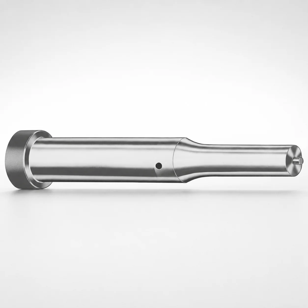
Metric Ejector Punches XNT DayTiN® Coating
Metric ejector punches (XNT DayTiN® coating) deliver reliable ejection in stamping and progressive dies. The DAYTON coating system helps resist wear while maintaining stable operation under repeated cycles.
- Metric ejector punch geometry for controlled straight-line part ejection
- XNT DayTiN® coating supports improved surface durability in production
- Consistent tip and shank design options help maintain fit in die cavities
- Built for metric die tooling applications where punch life matters
Specifications
368 configurations available
| Tip shape | Material | D (Shank dia.) (mm) | Jektole group | L1 (Point Length) (mm) | L (Length) (mm) | P Dimension (mm) | W Dimension (mm) | R Dimension (mm) |
|---|---|---|---|---|---|---|---|---|
| H | M2 | 05 | J2M | 13 ~ 19 | 40 ~ 80 | 1.6 ~ 4.95 | 1.6 ~ 4.95 | - |
| H | PS | 05 | J2M | 13 ~ 19 | 40 ~ 80 | 1.6 ~ 4.95 | 1.6 ~ 4.95 | - |
| H | M2 | 06 | J3M | 13 ~ 19 | 40 ~ 100 | 2 ~ 5.95 | 2 ~ 2.39 | - |
| H | M2 | 06 | J3M | 13 ~ 19 | 40 ~ 100 | 2 ~ 5.95 | 2.4 ~ 5.95 | - |
| H | PS | 06 | J3M | 13 ~ 19 | 40 ~ 100 | 2 ~ 5.95 | 2 ~ 2.39 | - |
| H | PS | 06 | J3M | 13 ~ 19 | 40 ~ 100 | 2 ~ 5.95 | 2.4 ~ 5.95 | - |
| H | M2 | 08 | J4M | 19 ~ 25 | 50 ~ 100 | 3 ~ 7.95 | 3 ~ 3.19 | - |
| H | M2 | 08 | J4M | 19 ~ 25 | 50 ~ 100 | 3 ~ 7.95 | 3.2 ~ 7.95 | - |
| H | PS | 08 | J4M | 19 ~ 25 | 50 ~ 100 | 3 ~ 7.95 | 3 ~ 3.19 | - |
| H | PS | 08 | J4M | 19 ~ 25 | 50 ~ 100 | 3 ~ 7.95 | 3.2 ~ 7.95 | - |
| H | M2 | 10 | J6M | 19 ~ 25 | 50 ~ 100 | 4 ~ 9.95 | 4 ~ 4.49 | - |
| H | M2 | 10 | J6M | 19 ~ 25 | 50 ~ 100 | 4 ~ 9.95 | 4.5 ~ 9.95 | - |
| H | PS | 10 | J6M | 19 ~ 25 | 50 ~ 100 | 4 ~ 9.95 | 4 ~ 4.49 | - |
| H | PS | 10 | J6M | 19 ~ 25 | 50 ~ 100 | 4 ~ 9.95 | 4.5 ~ 9.95 | - |
| H | M2 | 13 | J6M | 19 ~ 25 | 50 ~ 100 | 4 ~ 12.95 | 4 ~ 5.99 | - |
| H | M2 | 13 | J6M | 19 ~ 25 | 50 ~ 100 | 4 ~ 12.95 | 6 ~ 12.95 | - |
| H | PS | 13 | J6M | 19 ~ 25 | 50 ~ 100 | 4 ~ 12.95 | 4 ~ 5.99 | - |
| H | PS | 13 | J6M | 19 ~ 25 | 50 ~ 100 | 4 ~ 12.95 | 6 ~ 12.95 | - |
| H | M2 | 16 | J9M | 19 ~ 25 | 50 ~ 100 | 6 ~ 15.95 | 6 ~ 7.19 | - |
| H | M2 | 16 | J9M | 19 ~ 25 | 50 ~ 100 | 6 ~ 15.95 | 7.2 ~ 15.95 | - |
| H | PS | 16 | J9M | 19 ~ 25 | 50 ~ 100 | 6 ~ 15.95 | 6 ~ 7.19 | - |
| H | PS | 16 | J9M | 19 ~ 25 | 50 ~ 100 | 6 ~ 15.95 | 7.2 ~ 15.95 | - |
| H | M2 | 20 | J9M | 19 ~ 25 | 50 ~ 100 | 6 ~ 19.95 | 6 ~ 7.99 | - |
| H | M2 | 20 | J9M | 19 ~ 25 | 50 ~ 100 | 6 ~ 19.95 | 8 ~ 19.95 | - |
| H | PS | 20 | J9M | 19 ~ 25 | 50 ~ 100 | 6 ~ 19.95 | 6 ~ 7.99 | - |
| H | PS | 20 | J9M | 19 ~ 25 | 50 ~ 100 | 6 ~ 19.95 | 8 ~ 19.95 | - |
| H | M2 | 25 | J9M | 19 ~ 25 | 50 ~ 100 | 6 ~ 24.95 | 6 ~ 8.99 | - |
| H | M2 | 25 | J9M | 19 ~ 25 | 50 ~ 100 | 6 ~ 24.95 | 9 ~ 24.95 | - |
| H | PS | 25 | J9M | 19 ~ 25 | 50 ~ 100 | 6 ~ 24.95 | 6 ~ 8.99 | - |
| H | PS | 25 | J9M | 19 ~ 25 | 50 ~ 100 | 6 ~ 24.95 | 9 ~ 24.95 | - |
| H | M2 | 32 | J12M | 25 ~ 30 | 63 ~ 100 | 7.2 ~ 31.95 | 7.2 ~ 9.99 | - |
| H | M2 | 32 | J12M | 25 ~ 30 | 63 ~ 100 | 7.2 ~ 31.95 | 10 ~ 31.95 | - |
| H | PS | 32 | J12M | 25 ~ 30 | 63 ~ 100 | 7.2 ~ 31.95 | 7.2 ~ 9.99 | - |
| H | PS | 32 | J12M | 25 ~ 30 | 63 ~ 100 | 7.2 ~ 31.95 | 10 ~ 31.95 | - |
| J | M2 | 05 | J2M | 13 ~ 19 | 40 ~ 80 | 1.6 ~ 4.95 | 1.6 ~ 4.95 | - |
| J | PS | 05 | J2M | 13 ~ 19 | 40 ~ 80 | 1.6 ~ 4.95 | 1.6 ~ 4.95 | - |
| J | M2 | 06 | J3M | 13 ~ 19 | 40 ~ 100 | 2 ~ 5.95 | 2 ~ 2.39 | - |
| J | M2 | 06 | J3M | 13 ~ 19 | 40 ~ 100 | 2 ~ 5.95 | 2.4 ~ 5.95 | - |
| J | PS | 06 | J3M | 13 ~ 19 | 40 ~ 100 | 2 ~ 5.95 | 2 ~ 2.39 | - |
| J | PS | 06 | J3M | 13 ~ 19 | 40 ~ 100 | 2 ~ 5.95 | 2.4 ~ 5.95 | - |
| J | M2 | 08 | J4M | 19 ~ 25 | 50 ~ 100 | 3 ~ 7.95 | 3 ~ 3.19 | - |
| J | M2 | 08 | J4M | 19 ~ 25 | 50 ~ 100 | 3 ~ 7.95 | 3.2 ~ 7.95 | - |
| J | PS | 08 | J4M | 19 ~ 25 | 50 ~ 100 | 3 ~ 7.95 | 3 ~ 3.19 | - |
| J | PS | 08 | J4M | 19 ~ 25 | 50 ~ 100 | 3 ~ 7.95 | 3.2 ~ 7.95 | - |
| J | M2 | 10 | J6M | 19 ~ 25 | 50 ~ 100 | 4 ~ 9.95 | 4 ~ 4.49 | - |
| J | M2 | 10 | J6M | 19 ~ 25 | 50 ~ 100 | 4 ~ 9.95 | 4.5 ~ 9.95 | - |
| J | PS | 10 | J6M | 19 ~ 25 | 50 ~ 100 | 4 ~ 9.95 | 4 ~ 4.49 | - |
| J | PS | 10 | J6M | 19 ~ 25 | 50 ~ 100 | 4 ~ 9.95 | 4.5 ~ 9.95 | - |
| J | M2 | 13 | J6M | 19 ~ 25 | 50 ~ 100 | 4 ~ 12.95 | 4 ~ 5.99 | - |
| J | M2 | 13 | J6M | 19 ~ 25 | 50 ~ 100 | 4 ~ 12.95 | 6 ~ 12.95 | - |
Product Guide
Application Scenarios+
Metric ejector punches with the XNT DayTiN® coating are used in stamping and progressive die sets where parts must separate cleanly from the tooling after each forming cycle. Their straight-line, controlled punch geometry supports predictable ejection and reduces the risk of sticking or drag marks on the part surface.
In automotive connector and terminal stamping, repeated cycling and abrasive debris demand high wear resistance. The DayTiN® coating improves surface durability at the punch working end, helping maintain stable ejection force and alignment over long production runs.
For small-batch electronics housings and brackets, these metric punches fit common die standards and provide a consistent tip profile selection (H, J, K, L, N, O, R, V, X, Y, Z). Choosing appropriate shank diameters and point lengths helps ensure the punch reaches the correct ejection depth without excessive protrusion.
- Progressive dies: stable ejection under repeated cycles
- High-wear stamping zones: improved tool life via DayTiN®
- Metric die tooling: selectable tip shapes for controlled separation
Material & Process Details+
This series is offered in M2 or PS steel options, with the XNT DayTiN® coating applied for wear reduction at the contact zone. M2 (a high-speed steel) is selected when toughness and wear resistance are both critical in punch service, particularly where abrasive scale or debris accelerates wear.
PS is typically chosen for applications emphasizing cost-effective tool life while still benefiting from the hard coating at the working surfaces. Both material choices rely on the coating system to improve surface durability, but they can differ in balance between wear resistance and toughness under cyclic loading.
- Coating state: XNT DayTiN® finished punches (surface-enhanced for the punch tip and shank working areas)
- Hardness: not specified in the provided data—selection is typically based on the steel/coating combination and required ejection duty
- Wear vs. toughness: M2 generally provides higher wear capability; PS may be preferable where toughness demand is moderate
Sizing & Selection Guide+
Select the metric ejector punch dimensions by matching the required ejection depth, contact geometry, and clearance within the die set. Start with the shank diameter D from 5 ~ 32 mm to ensure proper alignment in the guide/bushing and to maintain stable straight-line ejection.
Next, choose the tip point length L1 from 13 ~ 19, 19 ~ 25, or 25 ~ 30 mm based on how far the punch must extend into the part separation zone. Then select overall punch length L from the available ranges (40 ~ 80, 40 ~ 100, 50 ~ 100, or 63 ~ 100 mm) so the punch fully engages during actuation while allowing correct return stroke.
- Pick tip shape (H/J/K/L/N/O/R/V/X/Y/Z) for the desired contact footprint
- Verify pocket/clearance using P (1.3 ~ 16 mm) and W (1.6 ~ 10 mm)
- Confirm corner radius R = 0.2 mm for consistent contact behavior
Tolerance/fit: match D to your die guide/bushing bore with the intended running clearance; this data sheet provides dimension ranges but does not specify tolerances—use your die standard for final fit.
Frequently Asked Questions
Which tip shapes (H, J, K, L, N, O, R, V, X, Y, Z) should I choose to control ejection contact in progressive dies?+
How do I match shank diameter D to my die guide system when using metric ejector punches?+
What are the recommended point length L1 and overall length L ranges for correct ejection depth and stroke?+
What coating advantage does XNT DayTiN® provide for ejector punch wear during high-cycle stamping?+
Should I choose M2 or PS steel for my ejector punch application with DayTiN® coating?+
Related Products






Need Custom Specifications?
Our engineering team can help with custom configurations, material selection, and volume pricing.