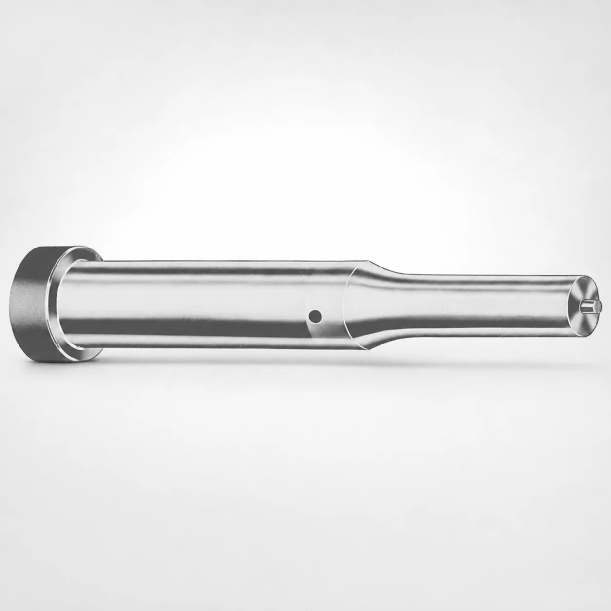
Metric Ejector Punches with XNP Coating
Metric ejector punches with XNP coating from DAYTON are precision die components designed for reliable material ejection. The XNP coating package helps improve surface durability for long production runs and stable punch performance.
- Standard metric ejector punch geometry for die and punch press tooling
- XNP coating option supports abrasion resistance in demanding cycles
- Selectable tip shapes support different point engagement requirements
- Used for forming, trimming, and blanking dies requiring consistent ejection
Specifications
367 configurations available
| Tip shape | Material | D (Shank dia.) (mm) | Jektole group | L1 (Point Length) (mm) | L (Length) (mm) | P Dimension (mm) | W Dimension (mm) | R Dimension (mm) |
|---|---|---|---|---|---|---|---|---|
| H | M2 | 05 | J2M | 13 ~ 19 | 40 ~ 80 | 1.6 ~ 4.95 | 1.6 ~ 4.95 | - |
| H | PS | 05 | J2M | 13 ~ 19 | 40 ~ 80 | 1.6 ~ 4.95 | 1.6 ~ 4.95 | - |
| H | M2 | 06 | J3M | 13 ~ 19 | 40 ~ 100 | 2 ~ 5.95 | 2 ~ 2.39 | - |
| H | M2 | 06 | J3M | 13 ~ 19 | 40 ~ 100 | 2 ~ 5.95 | 2.4 ~ 5.95 | - |
| H | PS | 06 | J3M | 13 ~ 19 | 40 ~ 100 | 2 ~ 5.95 | 2 ~ 2.39 | - |
| H | PS | 06 | J3M | 13 ~ 19 | 40 ~ 100 | 2 ~ 5.95 | 2.4 ~ 5.95 | - |
| H | M2 | 08 | J4M | 19 ~ 25 | 50 ~ 100 | 3 ~ 7.95 | 3 ~ 3.19 | - |
| H | M2 | 08 | J4M | 19 ~ 25 | 50 ~ 100 | 3 ~ 7.95 | 3.2 ~ 7.95 | - |
| H | PS | 08 | J4M | 19 ~ 25 | 50 ~ 100 | 3 ~ 7.95 | 3 ~ 3.19 | - |
| H | PS | 08 | J4M | 19 ~ 25 | 50 ~ 100 | 3 ~ 7.95 | 3.2 ~ 7.95 | - |
| H | M2 | 10 | J6M | 19 ~ 25 | 50 ~ 100 | 4 ~ 9.95 | 4 ~ 4.49 | - |
| H | M2 | 10 | J6M | 19 ~ 25 | 50 ~ 100 | 4 ~ 9.95 | 4.5 ~ 9.95 | - |
| H | PS | 10 | J6M | 19 ~ 25 | 50 ~ 100 | 4 ~ 9.95 | 4 ~ 4.49 | - |
| H | PS | 10 | J6M | 19 ~ 25 | 50 ~ 100 | 4 ~ 9.95 | 4.5 ~ 9.95 | - |
| H | M2 | 13 | J6M | 19 ~ 25 | 50 ~ 100 | 4 ~ 12.95 | 4 ~ 5.99 | - |
| H | M2 | 13 | J6M | 19 ~ 25 | 50 ~ 100 | 4 ~ 12.95 | 6 ~ 12.95 | - |
| H | PS | 13 | J6M | 19 ~ 25 | 50 ~ 100 | 4 ~ 12.95 | 4 ~ 5.99 | - |
| H | PS | 13 | J6M | 19 ~ 25 | 50 ~ 100 | 4 ~ 12.95 | 6 ~ 12.95 | - |
| H | M2 | 16 | J9M | 19 ~ 25 | 50 ~ 100 | 6 ~ 15.95 | 6 ~ 7.19 | - |
| H | M2 | 16 | J9M | 19 ~ 25 | 50 ~ 100 | 6 ~ 15.95 | 7.2 ~ 15.95 | - |
| H | PS | 16 | J9M | 19 ~ 25 | 50 ~ 100 | 6 ~ 15.95 | 6 ~ 7.19 | - |
| H | PS | 16 | J9M | 19 ~ 25 | 50 ~ 100 | 6 ~ 15.95 | 7.2 ~ 15.95 | - |
| H | M2 | 20 | J9M | 19 ~ 25 | 50 ~ 100 | 6 ~ 19.95 | 6 ~ 7.99 | - |
| H | M2 | 20 | J9M | 19 ~ 25 | 50 ~ 100 | 6 ~ 19.95 | 8 ~ 19.95 | - |
| H | PS | 20 | J9M | 19 ~ 25 | 50 ~ 100 | 6 ~ 19.95 | 6 ~ 7.99 | - |
| H | PS | 20 | J9M | 19 ~ 25 | 50 ~ 100 | 6 ~ 19.95 | 8 ~ 19.95 | - |
| H | M2 | 25 | J9M | 19 ~ 25 | 50 ~ 100 | 6 ~ 24.95 | 6 ~ 8.99 | - |
| H | M2 | 25 | J9M | 19 ~ 25 | 50 ~ 100 | 6 ~ 24.95 | 9 ~ 24.95 | - |
| H | PS | 25 | J9M | 19 ~ 25 | 50 ~ 100 | 6 ~ 24.95 | 6 ~ 8.99 | - |
| H | PS | 25 | J9M | 19 ~ 25 | 50 ~ 100 | 6 ~ 24.95 | 9 ~ 24.95 | - |
| H | M2 | 32 | J12M | 25 ~ 30 | 63 ~ 100 | 7.2 ~ 31.95 | 7.2 ~ 9.99 | - |
| H | M2 | 32 | J12M | 25 ~ 30 | 63 ~ 100 | 7.2 ~ 31.95 | 10 ~ 31.95 | - |
| H | PS | 32 | J12M | 25 ~ 30 | 63 ~ 100 | 7.2 ~ 31.95 | 7.2 ~ 9.99 | - |
| H | PS | 32 | J12M | 25 ~ 30 | 63 ~ 100 | 7.2 ~ 31.95 | 10 ~ 31.95 | - |
| J | M2 | 05 | J2M | 13 ~ 19 | 40 ~ 80 | 1.6 ~ 4.95 | 1.6 ~ 4.95 | - |
| J | PS | 05 | J2M | 13 ~ 19 | 40 ~ 80 | 1.6 ~ 4.95 | 1.6 ~ 4.95 | - |
| J | M2 | 06 | J3M | 13 ~ 19 | 40 ~ 100 | 2 ~ 5.95 | 2 ~ 2.39 | - |
| J | M2 | 06 | J3M | 13 ~ 19 | 40 ~ 100 | 2 ~ 5.95 | 2.4 ~ 5.95 | - |
| J | PS | 06 | J3M | 13 ~ 19 | 40 ~ 100 | 2 ~ 5.95 | 2 ~ 2.39 | - |
| J | PS | 06 | J3M | 13 ~ 19 | 40 ~ 100 | 2 ~ 5.95 | 2.4 ~ 5.95 | - |
| J | M2 | 08 | J4M | 19 ~ 25 | 50 ~ 100 | 3 ~ 7.95 | 3 ~ 3.19 | - |
| J | M2 | 08 | J4M | 19 ~ 25 | 50 ~ 100 | 3 ~ 7.95 | 3.2 ~ 7.95 | - |
| J | PS | 08 | J4M | 19 ~ 25 | 50 ~ 100 | 3 ~ 7.95 | 3 ~ 3.19 | - |
| J | PS | 08 | J4M | 19 ~ 25 | 50 ~ 100 | 3 ~ 7.95 | 3.2 ~ 7.95 | - |
| J | M2 | 10 | J6M | 19 ~ 25 | 50 ~ 100 | 4 ~ 9.95 | 4 ~ 4.49 | - |
| J | M2 | 10 | J6M | 19 ~ 25 | 50 ~ 100 | 4 ~ 9.95 | 4.5 ~ 9.95 | - |
| J | PS | 10 | J6M | 19 ~ 25 | 50 ~ 100 | 4 ~ 9.95 | 4 ~ 4.49 | - |
| J | PS | 10 | J6M | 19 ~ 25 | 50 ~ 100 | 4 ~ 9.95 | 4.5 ~ 9.95 | - |
| J | M2 | 13 | J6M | 19 ~ 25 | 50 ~ 100 | 4 ~ 12.95 | 4 ~ 5.99 | - |
| J | M2 | 13 | J6M | 19 ~ 25 | 50 ~ 100 | 4 ~ 12.95 | 6 ~ 12.95 | - |
Product Guide
Application Scenarios+
This metric ejector punch line is used in injection mold and die tooling wherever parts must be ejected with repeatable force and consistent clearance. In automotive connector and housing molds, stable point engagement helps the punch transmit ejection loads without skidding, supporting uniform part release during high-cycle production.
For medical device housings and small inserts, engineers often select an ejector punch variant based on point length and overall length to match tight cavity-to-part spacing, improving control of knockout depth and reducing risk of surface marking.
In forming, trimming, and blanking dies, the selectable shank diameter and tip shape options allow tuning of contact area to match material thickness and cut geometry. The XNP coating package is suited for these demanding cycles because it is intended to improve surface durability and abrasion resistance, helping maintain ejection performance over long runs.
- Choose tip shape to match point engagement requirements
- Select point length (L1) and length (L) to control knockout depth
- Use shank diameter (D) to fit ejector layout and withstand press loads
Material & Process Details+
These punches are offered in M2 and PS material options, allowing selection based on wear vs. toughness requirements. M2 is a high-speed steel widely used for wear resistance; typical heat treatment is quench and temper after hardening, producing a hard surface suitable for repetitive contact and abrasion.
PS provides an alternative balance for tooling environments where controlled toughness and machining behavior are important. Exact hardness (HRC) values are not provided in the available specifications, so hardness selection should follow your internal material acceptance criteria for M2/PS and the coating target.
- XNP coating is applied to improve surface durability and abrasion resistance in demanding cycles.
- Trade-off: higher wear resistance materials typically require careful alignment of point shape and shank diameter to avoid edge chipping under shock loads.
- After heat treatment, the coated surface is intended to support stable punch performance during long production runs.
Sizing & Selection Guide+
Correct dimension matching is critical for stable ejection and to prevent misalignment in the ejector system. Start with the shank diameter D (5–32 mm) to confirm fit within the ejector bushing/hole size and to maintain concentricity with the mold cavity/core.
Next, select the point length L1 (13–19 mm, 19–25 mm, 25–30 mm) to set the effective knockout penetration. Longer L1 values increase engagement length, which can improve load distribution for deeper cavities but may be unsuitable for limited clearance.
Then choose the overall length L based on your ejector stroke and guide length requirements (available ranges include 40–80, 40–100, 50–100, and 63–100 mm).
- Match Jektole group (J2M/J3M/J4M/J6M/J9M/J12M) to your ejector layout standard.
- Select tip shape (H/J/K/L/N/O/R/V/X/Y/Z) to match required contact geometry.
- Verify dimensions P (1.3–16 mm) and W (1.6–10 mm) against part support and clearance zones.
Tolerance/fit note: use your mold-maker’s standard tolerances for hole/guides; confirm that the selected D and point profile will not bind during thermal expansion and full stroke.
Frequently Asked Questions
Which tip shapes (H, J, K, L, N, O, R, V, X, Y, Z) should be selected to improve ejector engagement stability?+
Tip shapes are selected based on the desired point engagement geometry and the risk of skidding during ejection. In practice, engineers choose a tip shape that matches the part’s release surface and the available clearance to control contact area. Confirm that the selected tip shape pairs with your required L1 (13–19, 19–25, or 25–30 mm) to avoid insufficient penetration or overtravel.
How do I determine the correct point length L1 for a metric ejector punch build?+
Use the available L1 options (13–19 mm, 19–25 mm, 25–30 mm) to control effective knockout penetration. Shorter L1 helps when cavity-to-part spacing is limited, while longer L1 can distribute load over a greater engagement length. Ensure L1 selection aligns with your intended ejector stroke and does not exceed clearance when the punch fully advances.
What are the available shank diameter D ranges and why do they matter for mold alignment?+
The shank diameter D ranges from 5 to 32 mm. This dimension determines how the punch fits into ejector guides/bushings and directly affects concentricity and stability. When selecting D, confirm it matches your ejector layout hole size and consider fit changes due to thermal expansion during production.
How do M2 and PS material choices affect performance when combined with the XNP coating?+
Material is offered as M2 or PS, and the product includes an XNP coating intended to improve surface durability and abrasion resistance. Choose M2 when wear resistance under repetitive contact is prioritized, and choose PS when an alternative balance of properties is required for your tooling environment. Because hardness (HRC) values are not listed here, validate hardness to your internal spec for the chosen grade.
Which overall length L should I select from the available ranges (40–80, 40–100, 50–100, 63–100 mm)?+
Select L based on the available guide length and required ejector stroke. Available options include 40–80, 40–100, 50–100, and 63–100 mm, so choose the smallest length that satisfies full-stroke support without bottoming out. Verify that the chosen L also fits your ejector stack-up while maintaining adequate clearance during cycling.
Related Products






Need Custom Specifications?
Our engineering team can help with custom configurations, material selection, and volume pricing.