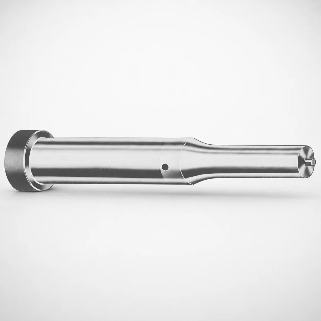
Metric XNM Coated Ejector Punches
Metric XNM coated ejector punches are designed for precise ejection in die and mold builds, helping maintain stable punch performance under repeated production cycles. Suitable for metric toolmaking where dependable surface protection matters.
- Metric shank ejector punch geometry supports consistent ejection timing
- XNM coating improves wear resistance for demanding molding operations
- Available tip shape options (X, R, K, O, H, L, J, N, V, Y, Z) for application matching
- Built for close-space production setups requiring compact punch form factors
Specifications
367 configurations available
| Tip shape | Material | D (Shank dia.) (mm) | Jektole group | L1 (Point Length) (mm) | L (Length) (mm) | P Dimension (mm) | W Dimension (mm) | R Dimension (mm) |
|---|---|---|---|---|---|---|---|---|
| H | M2 | 05 | J2M | 13 ~ 19 | 40 ~ 80 | 1.6 ~ 4.95 | 1.6 ~ 4.95 | - |
| H | PS | 05 | J2M | 13 ~ 19 | 40 ~ 80 | 1.6 ~ 4.95 | 1.6 ~ 4.95 | - |
| H | M2 | 06 | J3M | 13 ~ 19 | 40 ~ 100 | 2 ~ 5.95 | 2 ~ 2.39 | - |
| H | M2 | 06 | J3M | 13 ~ 19 | 40 ~ 100 | 2 ~ 5.95 | 2.4 ~ 5.95 | - |
| H | PS | 06 | J3M | 13 ~ 19 | 40 ~ 100 | 2 ~ 5.95 | 2 ~ 2.39 | - |
| H | PS | 06 | J3M | 13 ~ 19 | 40 ~ 100 | 2 ~ 5.95 | 2.4 ~ 5.95 | - |
| H | M2 | 08 | J4M | 19 ~ 25 | 50 ~ 100 | 3 ~ 7.95 | 3 ~ 3.19 | - |
| H | M2 | 08 | J4M | 19 ~ 25 | 50 ~ 100 | 3 ~ 7.95 | 3.2 ~ 7.95 | - |
| H | PS | 08 | J4M | 19 ~ 25 | 50 ~ 100 | 3 ~ 7.95 | 3 ~ 3.19 | - |
| H | PS | 08 | J4M | 19 ~ 25 | 50 ~ 100 | 3 ~ 7.95 | 3.2 ~ 7.95 | - |
| H | M2 | 10 | J6M | 19 ~ 25 | 50 ~ 100 | 4 ~ 9.95 | 4 ~ 4.49 | - |
| H | M2 | 10 | J6M | 19 ~ 25 | 50 ~ 100 | 4 ~ 9.95 | 4.5 ~ 9.95 | - |
| H | PS | 10 | J6M | 19 ~ 25 | 50 ~ 100 | 4 ~ 9.95 | 4 ~ 4.49 | - |
| H | PS | 10 | J6M | 19 ~ 25 | 50 ~ 100 | 4 ~ 9.95 | 4.5 ~ 9.95 | - |
| H | M2 | 13 | J6M | 19 ~ 25 | 50 ~ 100 | 4 ~ 12.95 | 4 ~ 5.99 | - |
| H | M2 | 13 | J6M | 19 ~ 25 | 50 ~ 100 | 4 ~ 12.95 | 6 ~ 12.95 | - |
| H | PS | 13 | J6M | 19 ~ 25 | 50 ~ 100 | 4 ~ 12.95 | 4 ~ 5.99 | - |
| H | PS | 13 | J6M | 19 ~ 25 | 50 ~ 100 | 4 ~ 12.95 | 6 ~ 12.95 | - |
| H | M2 | 16 | J9M | 19 ~ 25 | 50 ~ 100 | 6 ~ 15.95 | 6 ~ 7.19 | - |
| H | M2 | 16 | J9M | 19 ~ 25 | 50 ~ 100 | 6 ~ 15.95 | 7.2 ~ 15.95 | - |
| H | PS | 16 | J9M | 19 ~ 25 | 50 ~ 100 | 6 ~ 15.95 | 6 ~ 7.19 | - |
| H | PS | 16 | J9M | 19 ~ 25 | 50 ~ 100 | 6 ~ 15.95 | 7.2 ~ 15.95 | - |
| H | M2 | 20 | J9M | 19 ~ 25 | 50 ~ 100 | 6 ~ 19.95 | 6 ~ 7.99 | - |
| H | M2 | 20 | J9M | 19 ~ 25 | 50 ~ 100 | 6 ~ 19.95 | 8 ~ 19.95 | - |
| H | PS | 20 | J9M | 19 ~ 25 | 50 ~ 100 | 6 ~ 19.95 | 6 ~ 7.99 | - |
| H | PS | 20 | J9M | 19 ~ 25 | 50 ~ 100 | 6 ~ 19.95 | 8 ~ 19.95 | - |
| H | M2 | 25 | J9M | 19 ~ 25 | 50 ~ 100 | 6 ~ 24.95 | 6 ~ 8.99 | - |
| H | M2 | 25 | J9M | 19 ~ 25 | 50 ~ 100 | 6 ~ 24.95 | 9 ~ 24.95 | - |
| H | PS | 25 | J9M | 19 ~ 25 | 50 ~ 100 | 6 ~ 24.95 | 6 ~ 8.99 | - |
| H | PS | 25 | J9M | 19 ~ 25 | 50 ~ 100 | 6 ~ 24.95 | 9 ~ 24.95 | - |
| H | M2 | 32 | J12M | 25 ~ 30 | 63 ~ 100 | 7.2 ~ 31.95 | 7.2 ~ 9.99 | - |
| H | M2 | 32 | J12M | 25 ~ 30 | 63 ~ 100 | 7.2 ~ 31.95 | 10 ~ 31.95 | - |
| H | PS | 32 | J12M | 25 ~ 30 | 63 ~ 100 | 7.2 ~ 31.95 | 7.2 ~ 9.99 | - |
| H | PS | 32 | J12M | 25 ~ 30 | 63 ~ 100 | 7.2 ~ 31.95 | 10 ~ 31.95 | - |
| J | M2 | 05 | J2M | 13 ~ 19 | 40 ~ 80 | 1.6 ~ 4.95 | 1.6 ~ 4.95 | - |
| J | PS | 05 | J2M | 13 ~ 19 | 40 ~ 80 | 1.6 ~ 4.95 | 1.6 ~ 4.95 | - |
| J | M2 | 06 | J3M | 13 ~ 19 | 40 ~ 100 | 2 ~ 5.95 | 2 ~ 2.39 | - |
| J | M2 | 06 | J3M | 13 ~ 19 | 40 ~ 100 | 2 ~ 5.95 | 2.4 ~ 5.95 | - |
| J | PS | 06 | J3M | 13 ~ 19 | 40 ~ 100 | 2 ~ 5.95 | 2 ~ 2.39 | - |
| J | PS | 06 | J3M | 13 ~ 19 | 40 ~ 100 | 2 ~ 5.95 | 2.4 ~ 5.95 | - |
| J | M2 | 08 | J4M | 19 ~ 25 | 50 ~ 100 | 3 ~ 7.95 | 3 ~ 3.19 | - |
| J | M2 | 08 | J4M | 19 ~ 25 | 50 ~ 100 | 3 ~ 7.95 | 3.2 ~ 7.95 | - |
| J | PS | 08 | J4M | 19 ~ 25 | 50 ~ 100 | 3 ~ 7.95 | 3 ~ 3.19 | - |
| J | PS | 08 | J4M | 19 ~ 25 | 50 ~ 100 | 3 ~ 7.95 | 3.2 ~ 7.95 | - |
| J | M2 | 10 | J6M | 19 ~ 25 | 50 ~ 100 | 4 ~ 9.95 | 4 ~ 4.49 | - |
| J | M2 | 10 | J6M | 19 ~ 25 | 50 ~ 100 | 4 ~ 9.95 | 4.5 ~ 9.95 | - |
| J | PS | 10 | J6M | 19 ~ 25 | 50 ~ 100 | 4 ~ 9.95 | 4 ~ 4.49 | - |
| J | PS | 10 | J6M | 19 ~ 25 | 50 ~ 100 | 4 ~ 9.95 | 4.5 ~ 9.95 | - |
| J | M2 | 13 | J6M | 19 ~ 25 | 50 ~ 100 | 4 ~ 12.95 | 4 ~ 5.99 | - |
| J | M2 | 13 | J6M | 19 ~ 25 | 50 ~ 100 | 4 ~ 12.95 | 6 ~ 12.95 | - |
Product Guide
Application Scenarios+
Metric XNM coated ejector punches are used in injection mold tooling where consistent ejection force and stable timing are required over long production runs. In automotive connector and bracket molds, these punches help maintain surface protection on the ejector system, reducing abrasive wear from repeatedly sliding ejector components and improving the smoothness of part release.
For consumer electronics housings and other thin-wall parts with tight ejection space, the available metric shank geometry and compact punch form factors support installation in restricted layouts while keeping ejection performance repeatable across cycles.
In die and mold builds handling mixed materials, engineers can match tip profiles (X, R, K, O, H, L, J, N, V, Y, Z) to the part texture and ejector contact area, helping distribute load and minimize localized stress. The XNM coating variant is suited when longer tool life and enhanced wear resistance are priorities under demanding molding conditions.
Material & Process Details+
These ejector punches are offered in two material options: M2 and PS, supporting different wear and toughness needs in die and mold applications. M2 is commonly selected for higher wear resistance performance, especially where punch tips see continuous sliding and repeated mechanical contact.
- M2: typically supplied in a quenched & tempered condition to balance hardness and toughness for durable ejection performance.
- PS: chosen when a more cost-effective or application-specific balance of strength and wear behavior is required for stable ejection cycles.
Hardness values and exact heat-treatment parameters (e.g., target HRC ranges, nitriding/depth) are not specified in the provided dataset, so final hardness confirmation should be taken from the material certificate for the selected stock. When selecting between grades, prioritize tip wear resistance for abrasive plastics and frequent cycles (often M2) versus application-driven toughness/processing considerations (often PS).
Sizing & Selection Guide+
Select the ejector punch dimensions by matching the required stroke length, mounting clearance, and tip contact geometry to your mold cavity/core layout. Start with the shank diameter D (available 5 ~ 32 mm) to fit your guide hole or receiver features without binding. Then choose the overall length L from the available ranges (40 ~ 80, 40 ~ 100, 50 ~ 100, 63 ~ 100), ensuring adequate engagement while maintaining safe clearance at full ejection travel.
- Confirm point length L1 for the needed tip penetration/contact (13 ~ 19, 19 ~ 25, 25 ~ 30 mm).
- Verify the contact geometry using P ( 1.3 ~ 16 mm) and W ( 1.6 ~ 10 mm), and note the provided R dimension = 0.2 mm for the profile radius consistency.
- Choose the tip shape (H, J, K, L, N, O, R, V, X, Y, Z) based on part surface and ejector footprint.
Tolerance guidance is not included in the dataset; for reliable fit, engineers should align hole/bushing clearance and punch straightness requirements to their own mold guide specs.
Frequently Asked Questions
Which tip shapes (X, R, K, O, H, L, J, N, V, Y, Z) are best for distributing ejection load on different part geometries?+
How do I choose shank diameter D and overall length L to fit my ejector layout without interference?+
What material should I select for longer wear life—M2 or PS—when using XNM coating?+
How do the geometric parameters P, W, and the fixed R = 0.2 mm affect punch contact and part release?+
How do Jektole groups (J2M, J3M, J4M, J6M, J9M, J12M) relate to compatibility with my existing punch system?+
Related Products






Need Custom Specifications?
Our engineering team can help with custom configurations, material selection, and volume pricing.