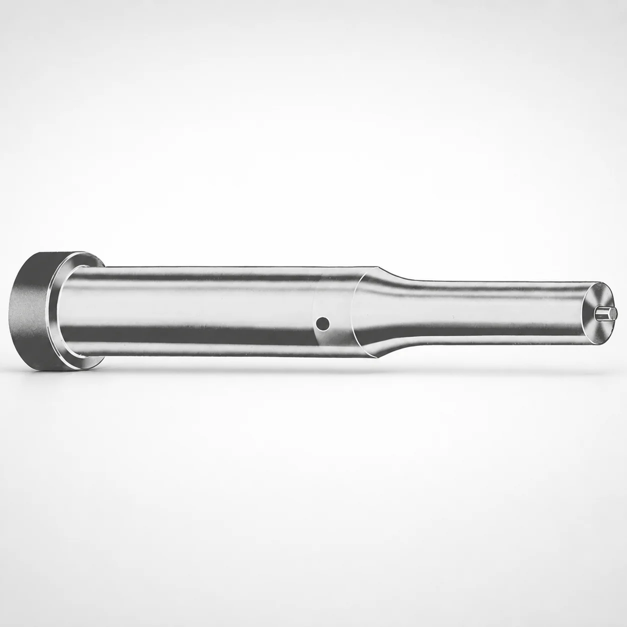
Metric Ejector Punches XNAP Coating
Metric ejector punches XNAP coating deliver stable ejection for precision tooling, combining a standardized geometry for smooth die operation with an effective surface protection system. Built for production environments where repeatability matters.
- Standardized metric punch format improves alignment and consistent ejection
- XNAP coating supports wear resistance and reduces galling risk
- Compatible with PS or M2 steel material options for tooling needs
- Available with multiple tip shapes (X, R, K, O, H, L, J, N, V, Y, Z) for design flexibility
Specifications
367 configurations available
| Tip shape | Material | D (Shank dia.) (mm) | Jektole group | L1 (Point Length) (mm) | L (Length) (mm) | P Dimension (mm) | W Dimension (mm) | R Dimension (mm) |
|---|---|---|---|---|---|---|---|---|
| H | M2 | 05 | J2M | 13 ~ 19 | 40 ~ 80 | 1.6 ~ 4.95 | 1.6 ~ 4.95 | - |
| H | PS | 05 | J2M | 13 ~ 19 | 40 ~ 80 | 1.6 ~ 4.95 | 1.6 ~ 4.95 | - |
| H | M2 | 06 | J3M | 13 ~ 19 | 40 ~ 100 | 2 ~ 5.95 | 2 ~ 2.39 | - |
| H | M2 | 06 | J3M | 13 ~ 19 | 40 ~ 100 | 2 ~ 5.95 | 2.4 ~ 5.95 | - |
| H | PS | 06 | J3M | 13 ~ 19 | 40 ~ 100 | 2 ~ 5.95 | 2 ~ 2.39 | - |
| H | PS | 06 | J3M | 13 ~ 19 | 40 ~ 100 | 2 ~ 5.95 | 2.4 ~ 5.95 | - |
| H | M2 | 08 | J4M | 19 ~ 25 | 50 ~ 100 | 3 ~ 7.95 | 3 ~ 3.19 | - |
| H | M2 | 08 | J4M | 19 ~ 25 | 50 ~ 100 | 3 ~ 7.95 | 3.2 ~ 7.95 | - |
| H | PS | 08 | J4M | 19 ~ 25 | 50 ~ 100 | 3 ~ 7.95 | 3 ~ 3.19 | - |
| H | PS | 08 | J4M | 19 ~ 25 | 50 ~ 100 | 3 ~ 7.95 | 3.2 ~ 7.95 | - |
| H | M2 | 10 | J6M | 19 ~ 25 | 50 ~ 100 | 4 ~ 9.95 | 4 ~ 4.49 | - |
| H | M2 | 10 | J6M | 19 ~ 25 | 50 ~ 100 | 4 ~ 9.95 | 4.5 ~ 9.95 | - |
| H | PS | 10 | J6M | 19 ~ 25 | 50 ~ 100 | 4 ~ 9.95 | 4 ~ 4.49 | - |
| H | PS | 10 | J6M | 19 ~ 25 | 50 ~ 100 | 4 ~ 9.95 | 4.5 ~ 9.95 | - |
| H | M2 | 13 | J6M | 19 ~ 25 | 50 ~ 100 | 4 ~ 12.95 | 4 ~ 5.99 | - |
| H | M2 | 13 | J6M | 19 ~ 25 | 50 ~ 100 | 4 ~ 12.95 | 6 ~ 12.95 | - |
| H | PS | 13 | J6M | 19 ~ 25 | 50 ~ 100 | 4 ~ 12.95 | 4 ~ 5.99 | - |
| H | PS | 13 | J6M | 19 ~ 25 | 50 ~ 100 | 4 ~ 12.95 | 6 ~ 12.95 | - |
| H | M2 | 16 | J9M | 19 ~ 25 | 50 ~ 100 | 6 ~ 15.95 | 6 ~ 7.19 | - |
| H | M2 | 16 | J9M | 19 ~ 25 | 50 ~ 100 | 6 ~ 15.95 | 7.2 ~ 15.95 | - |
| H | PS | 16 | J9M | 19 ~ 25 | 50 ~ 100 | 6 ~ 15.95 | 6 ~ 7.19 | - |
| H | PS | 16 | J9M | 19 ~ 25 | 50 ~ 100 | 6 ~ 15.95 | 7.2 ~ 15.95 | - |
| H | M2 | 20 | J9M | 19 ~ 25 | 50 ~ 100 | 6 ~ 19.95 | 6 ~ 7.99 | - |
| H | M2 | 20 | J9M | 19 ~ 25 | 50 ~ 100 | 6 ~ 19.95 | 8 ~ 19.95 | - |
| H | PS | 20 | J9M | 19 ~ 25 | 50 ~ 100 | 6 ~ 19.95 | 6 ~ 7.99 | - |
| H | PS | 20 | J9M | 19 ~ 25 | 50 ~ 100 | 6 ~ 19.95 | 8 ~ 19.95 | - |
| H | M2 | 25 | J9M | 19 ~ 25 | 50 ~ 100 | 6 ~ 24.95 | 6 ~ 8.99 | - |
| H | M2 | 25 | J9M | 19 ~ 25 | 50 ~ 100 | 6 ~ 24.95 | 9 ~ 24.95 | - |
| H | PS | 25 | J9M | 19 ~ 25 | 50 ~ 100 | 6 ~ 24.95 | 6 ~ 8.99 | - |
| H | PS | 25 | J9M | 19 ~ 25 | 50 ~ 100 | 6 ~ 24.95 | 9 ~ 24.95 | - |
| H | M2 | 32 | J12M | 25 ~ 30 | 63 ~ 100 | 7.2 ~ 31.95 | 7.2 ~ 9.99 | - |
| H | M2 | 32 | J12M | 25 ~ 30 | 63 ~ 100 | 7.2 ~ 31.95 | 10 ~ 31.95 | - |
| H | PS | 32 | J12M | 25 ~ 30 | 63 ~ 100 | 7.2 ~ 31.95 | 7.2 ~ 9.99 | - |
| H | PS | 32 | J12M | 25 ~ 30 | 63 ~ 100 | 7.2 ~ 31.95 | 10 ~ 31.95 | - |
| J | M2 | 05 | J2M | 13 ~ 19 | 40 ~ 80 | 1.6 ~ 4.95 | 1.6 ~ 4.95 | - |
| J | PS | 05 | J2M | 13 ~ 19 | 40 ~ 80 | 1.6 ~ 4.95 | 1.6 ~ 4.95 | - |
| J | M2 | 06 | J3M | 13 ~ 19 | 40 ~ 100 | 2 ~ 5.95 | 2 ~ 2.39 | - |
| J | M2 | 06 | J3M | 13 ~ 19 | 40 ~ 100 | 2 ~ 5.95 | 2.4 ~ 5.95 | - |
| J | PS | 06 | J3M | 13 ~ 19 | 40 ~ 100 | 2 ~ 5.95 | 2 ~ 2.39 | - |
| J | PS | 06 | J3M | 13 ~ 19 | 40 ~ 100 | 2 ~ 5.95 | 2.4 ~ 5.95 | - |
| J | M2 | 08 | J4M | 19 ~ 25 | 50 ~ 100 | 3 ~ 7.95 | 3 ~ 3.19 | - |
| J | M2 | 08 | J4M | 19 ~ 25 | 50 ~ 100 | 3 ~ 7.95 | 3.2 ~ 7.95 | - |
| J | PS | 08 | J4M | 19 ~ 25 | 50 ~ 100 | 3 ~ 7.95 | 3 ~ 3.19 | - |
| J | PS | 08 | J4M | 19 ~ 25 | 50 ~ 100 | 3 ~ 7.95 | 3.2 ~ 7.95 | - |
| J | M2 | 10 | J6M | 19 ~ 25 | 50 ~ 100 | 4 ~ 9.95 | 4 ~ 4.49 | - |
| J | M2 | 10 | J6M | 19 ~ 25 | 50 ~ 100 | 4 ~ 9.95 | 4.5 ~ 9.95 | - |
| J | PS | 10 | J6M | 19 ~ 25 | 50 ~ 100 | 4 ~ 9.95 | 4 ~ 4.49 | - |
| J | PS | 10 | J6M | 19 ~ 25 | 50 ~ 100 | 4 ~ 9.95 | 4.5 ~ 9.95 | - |
| J | M2 | 13 | J6M | 19 ~ 25 | 50 ~ 100 | 4 ~ 12.95 | 4 ~ 5.99 | - |
| J | M2 | 13 | J6M | 19 ~ 25 | 50 ~ 100 | 4 ~ 12.95 | 6 ~ 12.95 | - |
Product Guide
Application Scenarios+
Metric ejector punches are used in injection mold tooling to push formed parts off cavities during the ejection stroke. This variant is suited for production molds where repeatable part release and stable punch guidance are critical, thanks to its standardized metric geometry and wear-oriented surface protection.
In automotive and industrial connector molds, ejector punches with multiple available X-tip shapes and sizes (D 5–32 mm, L 40–100 mm ranges) help maintain consistent ejection force while minimizing surface damage from repeated cycles.
For consumer appliance housing molds and similar thin-to-medium wall parts, the ability to match point length to part thickness (L1 ranges such as 13–19, 19–25, and 25–30 mm) supports controlled contact without overtravel.
In medical device housings, selecting PS or M2 steel and the appropriate tip profile (H, J, K, L, N, O, R, V, X, Y, Z) allows tuning for dimensional stability and wear resistance under stringent, high-cycle molding conditions.
- Standardized metric format improves alignment and predictable ejection
- XNAP coating reduces galling risk and supports surface durability
- Tip-shape and length options enable contact optimization for different part geometries
Material & Process Details+
This ejector punch series is offered in PS and M2 steel options, allowing selection based on the wear and toughness balance needed for your molding application.
- M2 (tool steel): typically chosen for higher wear resistance in high-cycle environments where ejection surfaces see frequent rubbing and impact.
- PS (tool steel): selected when tooling performance requires a practical combination of strength and machining-friendly behavior while still benefiting from the XNAP surface protection.
The XNAP coating is the key differentiator for reducing galling and improving resistance against adhesive wear during repeated ejection. As with most punch steels, achieving final performance depends on the heat treatment state (commonly quenched & tempered for toughness or pre-hardened delivery followed by finishing). Exact hardness (HRC) and the specific heat treatment process are determined by the chosen steel option and manufacturer’s production route.
When choosing between PS and M2, prioritize M2 for maximum wear durability and PS when you need a more balanced, application-ready steel response under standard molding loads.
Sizing & Selection Guide+
To select the correct ejector punch, match the shank diameter (D) and overall length (L) to your mold’s guide and ejector system, then tune the contact geometry using tip shape and point length (L1).
Start with D = 5–32 mm. Ensure the selected D provides the intended fit with your ejector sleeve/retainer and maintains smooth alignment during the ejection stroke. Next confirm the available L range for your stack-up: examples include 40–80, 40–100, 50–100, or 63–100 mm, depending on the chosen group.
Then set the protrusion/contact using L1: options include 13–19, 19–25, and 25–30 mm. This helps control how much the punch engages the part and reduces the risk of overcontact or incomplete release.
- P (1.3–16 mm) and W (1.6–10 mm) support correct tip/point geometry for the selected tip profile
- R is specified at 0.2 mm for the radius-related feature
- Tip shape is configurable: H, J, K, L, N, O, R, V, X, Y, Z
Frequently Asked Questions
Which tip shapes are available for the metric ejector punches in this XNAP-coated series, and when should I choose X vs. R or O profiles?+
What diameter (D) and length (L) ranges can I specify for mold design compatibility?+
How do I select the correct point length (L1) for reliable ejection without overtravel?+
Should I choose PS or M2 steel for high-cycle ejection where galling and wear are concerns?+
Are the P, W, and R dimensions fixed in this series, and how do they affect tip geometry?+
Related Products






Need Custom Specifications?
Our engineering team can help with custom configurations, material selection, and volume pricing.