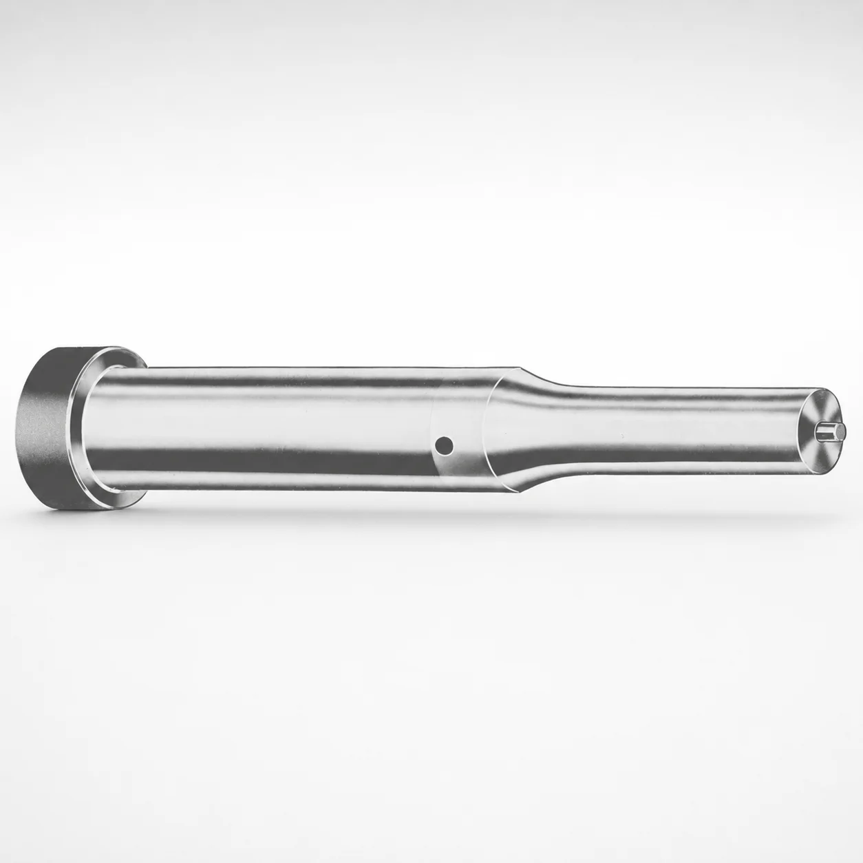
Ejector Punches - Metric, XN DayTride® Coating
Ejector Punches - Metric, XN DayTride® Coating are designed for reliable punch and eject performance, combining a controlled metric shank with a wear-resistant coating system. The coated surface helps reduce abrasion during repeated press cycles.
- XN DayTride® coating supports consistent wear resistance in tooling service
- Metric ejector punch geometry enables secure guidance for punch applications
- Tip shapes are available across multiple configurations (X, R, K, O, H)
- Suitable for metric die sets and production operations requiring stable ejection
Specifications
367 configurations available
| Tip shape | Material | D (Shank dia.) (mm) | Jektole group | L1 (Point Length) (mm) | L (Length) (mm) | P Dimension (mm) | W Dimension (mm) | R Dimension (mm) |
|---|---|---|---|---|---|---|---|---|
| H | M2 | 05 | J2M | 13 ~ 19 | 40 ~ 80 | 1.6 ~ 4.95 | 1.6 ~ 4.95 | - |
| H | PS | 05 | J2M | 13 ~ 19 | 40 ~ 80 | 1.6 ~ 4.95 | 1.6 ~ 4.95 | - |
| H | M2 | 06 | J3M | 13 ~ 19 | 40 ~ 100 | 2 ~ 5.95 | 2 ~ 2.39 | - |
| H | M2 | 06 | J3M | 13 ~ 19 | 40 ~ 100 | 2 ~ 5.95 | 2.4 ~ 5.95 | - |
| H | PS | 06 | J3M | 13 ~ 19 | 40 ~ 100 | 2 ~ 5.95 | 2 ~ 2.39 | - |
| H | PS | 06 | J3M | 13 ~ 19 | 40 ~ 100 | 2 ~ 5.95 | 2.4 ~ 5.95 | - |
| H | M2 | 08 | J4M | 19 ~ 25 | 50 ~ 100 | 3 ~ 7.95 | 3 ~ 3.19 | - |
| H | M2 | 08 | J4M | 19 ~ 25 | 50 ~ 100 | 3 ~ 7.95 | 3.2 ~ 7.95 | - |
| H | PS | 08 | J4M | 19 ~ 25 | 50 ~ 100 | 3 ~ 7.95 | 3 ~ 3.19 | - |
| H | PS | 08 | J4M | 19 ~ 25 | 50 ~ 100 | 3 ~ 7.95 | 3.2 ~ 7.95 | - |
| H | M2 | 10 | J6M | 19 ~ 25 | 50 ~ 100 | 4 ~ 9.95 | 4 ~ 4.49 | - |
| H | M2 | 10 | J6M | 19 ~ 25 | 50 ~ 100 | 4 ~ 9.95 | 4.5 ~ 9.95 | - |
| H | PS | 10 | J6M | 19 ~ 25 | 50 ~ 100 | 4 ~ 9.95 | 4 ~ 4.49 | - |
| H | PS | 10 | J6M | 19 ~ 25 | 50 ~ 100 | 4 ~ 9.95 | 4.5 ~ 9.95 | - |
| H | M2 | 13 | J6M | 19 ~ 25 | 50 ~ 100 | 4 ~ 12.95 | 4 ~ 5.99 | - |
| H | M2 | 13 | J6M | 19 ~ 25 | 50 ~ 100 | 4 ~ 12.95 | 6 ~ 12.95 | - |
| H | PS | 13 | J6M | 19 ~ 25 | 50 ~ 100 | 4 ~ 12.95 | 4 ~ 5.99 | - |
| H | PS | 13 | J6M | 19 ~ 25 | 50 ~ 100 | 4 ~ 12.95 | 6 ~ 12.95 | - |
| H | M2 | 16 | J9M | 19 ~ 25 | 50 ~ 100 | 6 ~ 15.95 | 6 ~ 7.19 | - |
| H | M2 | 16 | J9M | 19 ~ 25 | 50 ~ 100 | 6 ~ 15.95 | 7.2 ~ 15.95 | - |
| H | PS | 16 | J9M | 19 ~ 25 | 50 ~ 100 | 6 ~ 15.95 | 6 ~ 7.19 | - |
| H | PS | 16 | J9M | 19 ~ 25 | 50 ~ 100 | 6 ~ 15.95 | 7.2 ~ 15.95 | - |
| H | M2 | 20 | J9M | 19 ~ 25 | 50 ~ 100 | 6 ~ 19.95 | 6 ~ 7.99 | - |
| H | M2 | 20 | J9M | 19 ~ 25 | 50 ~ 100 | 6 ~ 19.95 | 8 ~ 19.95 | - |
| H | PS | 20 | J9M | 19 ~ 25 | 50 ~ 100 | 6 ~ 19.95 | 6 ~ 7.99 | - |
| H | PS | 20 | J9M | 19 ~ 25 | 50 ~ 100 | 6 ~ 19.95 | 8 ~ 19.95 | - |
| H | M2 | 25 | J9M | 19 ~ 25 | 50 ~ 100 | 6 ~ 24.95 | 6 ~ 8.99 | - |
| H | M2 | 25 | J9M | 19 ~ 25 | 50 ~ 100 | 6 ~ 24.95 | 9 ~ 24.95 | - |
| H | PS | 25 | J9M | 19 ~ 25 | 50 ~ 100 | 6 ~ 24.95 | 6 ~ 8.99 | - |
| H | PS | 25 | J9M | 19 ~ 25 | 50 ~ 100 | 6 ~ 24.95 | 9 ~ 24.95 | - |
| H | M2 | 32 | J12M | 25 ~ 30 | 63 ~ 100 | 7.2 ~ 31.95 | 7.2 ~ 9.99 | - |
| H | M2 | 32 | J12M | 25 ~ 30 | 63 ~ 100 | 7.2 ~ 31.95 | 10 ~ 31.95 | - |
| H | PS | 32 | J12M | 25 ~ 30 | 63 ~ 100 | 7.2 ~ 31.95 | 7.2 ~ 9.99 | - |
| H | PS | 32 | J12M | 25 ~ 30 | 63 ~ 100 | 7.2 ~ 31.95 | 10 ~ 31.95 | - |
| J | M2 | 05 | J2M | 13 ~ 19 | 40 ~ 80 | 1.6 ~ 4.95 | 1.6 ~ 4.95 | - |
| J | PS | 05 | J2M | 13 ~ 19 | 40 ~ 80 | 1.6 ~ 4.95 | 1.6 ~ 4.95 | - |
| J | M2 | 06 | J3M | 13 ~ 19 | 40 ~ 100 | 2 ~ 5.95 | 2 ~ 2.39 | - |
| J | M2 | 06 | J3M | 13 ~ 19 | 40 ~ 100 | 2 ~ 5.95 | 2.4 ~ 5.95 | - |
| J | PS | 06 | J3M | 13 ~ 19 | 40 ~ 100 | 2 ~ 5.95 | 2 ~ 2.39 | - |
| J | PS | 06 | J3M | 13 ~ 19 | 40 ~ 100 | 2 ~ 5.95 | 2.4 ~ 5.95 | - |
| J | M2 | 08 | J4M | 19 ~ 25 | 50 ~ 100 | 3 ~ 7.95 | 3 ~ 3.19 | - |
| J | M2 | 08 | J4M | 19 ~ 25 | 50 ~ 100 | 3 ~ 7.95 | 3.2 ~ 7.95 | - |
| J | PS | 08 | J4M | 19 ~ 25 | 50 ~ 100 | 3 ~ 7.95 | 3 ~ 3.19 | - |
| J | PS | 08 | J4M | 19 ~ 25 | 50 ~ 100 | 3 ~ 7.95 | 3.2 ~ 7.95 | - |
| J | M2 | 10 | J6M | 19 ~ 25 | 50 ~ 100 | 4 ~ 9.95 | 4 ~ 4.49 | - |
| J | M2 | 10 | J6M | 19 ~ 25 | 50 ~ 100 | 4 ~ 9.95 | 4.5 ~ 9.95 | - |
| J | PS | 10 | J6M | 19 ~ 25 | 50 ~ 100 | 4 ~ 9.95 | 4 ~ 4.49 | - |
| J | PS | 10 | J6M | 19 ~ 25 | 50 ~ 100 | 4 ~ 9.95 | 4.5 ~ 9.95 | - |
| J | M2 | 13 | J6M | 19 ~ 25 | 50 ~ 100 | 4 ~ 12.95 | 4 ~ 5.99 | - |
| J | M2 | 13 | J6M | 19 ~ 25 | 50 ~ 100 | 4 ~ 12.95 | 6 ~ 12.95 | - |
Product Guide
Application Scenarios+
These metric ejector punches are used in injection and compression tooling where reliable ejection and punch guidance are critical. In typical setups, they support the ejector plate in press cycles that demand stable straight-line motion and consistent tip wear characteristics.
Common scenarios include:
- Automotive and industrial connector housings: use the metric shank to maintain alignment in die sets, helping reduce mismatch-driven abrasion during high-frequency ejection.
- Appliance and consumer component molds: the XN DayTride® coating is selected to improve wear resistance on the punch/eject contact zones, supporting long production runs.
- General production die sets with standard punch requirements: choose the appropriate tip shape (X, R, K, O, H and others) to match the part geometry and eject action.
This variant’s metric geometry plus the wear-focused XN DayTride® coating makes it well suited for tooling that experiences repeated sliding and localized contact at the point.
Material & Process Details+
Material selection for these ejector punches is offered in M2 and PS, depending on the tool’s wear and toughness needs. M2 corresponds to a high-speed steel class (commonly referenced as AISI M2), which is known for strong wear resistance under repetitive contact. PS is a die steel option typically chosen when balancing machinability and performance for standard tooling.
Manufacturing and heat treatment follow standard hardened tooling practices for ejector/punch components:
- Quenched & tempered steels are used to achieve an optimized hardness/toughness trade-off for impact-prone ejection cycles.
- XN DayTride® coating is applied to the contact area to reduce abrasion during service.
When selecting between M2 and PS, engineers generally prefer M2 for higher wear-demand applications, while PS can be a practical choice where toughness and cost-effective tool life are prioritized. (Specific hardness in HRC is dependent on the ordered material state.)
Sizing & Selection Guide+
Select ejector punch dimensions by matching the shank diameter (D), point length (L1), and overall length (L) to the die set layout and the required penetration to eject the part.
- Shank diameter D (mm): choose from 5 ~ 32 to fit the ejector guide/bushing geometry and maintain alignment.
- Point length L1 (mm): select 13 ~ 19, 19 ~ 25, or 25 ~ 30 based on the required tip reach into the die/part interface.
- Total length L (mm): choose from 40 ~ 80, 40 ~ 100, 50 ~ 100, or 63 ~ 100 to ensure correct stroke engagement without overtravel.
Tip shape (H, J, K, L, N, O, R, V, X, Y, Z) must match the eject contact geometry. Ensure clearance and fit consistency in metric guided systems; order dimensions are fixed within the listed ranges, while the tolerance performance will be controlled by the press-fit/guide design and the tool’s manufactured specs for that selected size.
Frequently Asked Questions
Which tip shapes (H, J, K, L, N, O, R, V, X, Y, Z) should I choose for different ejector contact geometries?+
Tip shapes for this metric ejector punch family include H, J, K, L, N, O, R, V, X, Y, Z. Choose the geometry that best matches the part’s eject surface contact area to avoid stress concentration and uneven wear. If you share the part geometry and eject strategy (edge vs. point contact), the correct tip style can be selected alongside your required L1 range.
How do I match the shank diameter range (D = 5–32 mm) and overall length (L = 40–100 mm) to my die set layout?+
Select D from 5 ~ 32 mm to match the guiding/bushing diameter in the tool. Then choose L from the provided options (e.g., 40 ~ 80, 40 ~ 100, 50 ~ 100, 63 ~ 100) to ensure proper engagement across your stroke. Confirm the required tip reach with L1 (13–19, 19–25, or 25–30 mm) so the eject action is consistent without bottoming.
What material should I choose—M2 or PS—when wear resistance versus tool toughness is the priority?+
This product line is available in M2 or PS. M2 is commonly selected for higher wear resistance under repeated sliding/contact, while PS is used as a tooling steel option for balanced performance. Final hardness in HRC depends on the ordered material and heat treatment state provided by the manufacturer, so validate against your expected cycle rate and ejection loads.
How does the XN DayTride® coating impact punch wear for repeated ejection cycles?+
The ejector punch includes an XN DayTride® coating aimed at improving wear resistance at the contact zone. This helps reduce abrasion during repeated press cycles, supporting more consistent ejection performance. When you’re dealing with long production runs or abrasive contact regions, the coating is typically beneficial regardless of the chosen tip shape.
What are the key sizing parameters P (1.3–16 mm) and W (1.6–10 mm) for proper guidance and point geometry?+
This series provides additional geometry controls: P = 1.3 ~ 16 mm and W = 1.6 ~ 10 mm, along with a small R dimension = 0.2 mm. These dimensions influence the tip profile and how the punch interfaces with the part/die surface. Ensure P and W are selected consistently with your chosen tip shape and the available clearance in the mold cavity/core area.
Related Products






Need Custom Specifications?
Our engineering team can help with custom configurations, material selection, and volume pricing.